Carbide End Mill Guide: Choose the Right Tool Life & Surface Finish
Author: JYC Carbide Engineering Team | Reviewed by: Senior Process Engineer | Last updated: 2026
In most mold and precision job shops, the solid carbide end mill is the tool that stays in the spindle the longest. It cuts everything from pre‑hardened mold steel to stainless and aluminum, but the real question is not “can it cut?”—it is “how do we keep surface finish and tool life predictable?” This guide looks at carbide end mills from an engineering point of view so you can set realistic expectations instead of relying on “one‑tool‑does‑everything” marketing.


Which Features Are Carbide End Mills Really Suited For?
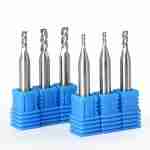
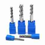
In this article, “carbide end mill” means solid carbide end mills used on machining centers and high‑speed mills: flat end mills, ball nose, corner radius, roughers, and long‑neck tools in standard metric sizes. These tools belong to the broader carbide end mill product family, which JYC Carbide designs for different materials and operations.
With sensible tool selection and parameters, carbide end mills can cover most of the milling features you see in a typical CNC shop. Typical features where solid carbide end mills work well include:
- Faces, steps, and side walls
- Standard pockets and slots, both open and closed
- Typical mold and die cavities with moderate depth
- Ribs, bosses, and thin‑wall structures with reasonable stiffness
- Cleanup of mating surfaces and shoulders
- Auxiliary moves such as ramping, helical entry, and chamfers
For extreme thin walls (for example, wall thickness under about 0.3 mm), very long reach over roughly 10–15×D, or very tight form and position tolerances on precision fits or mold inserts, you will usually combine carbide end mills with dedicated tooling, EDM, or grinding instead of expecting one end mill to complete every operation. A separate overview of common milling cutter types is available in JYC Carbide’s types of milling cutters guide.
Typical Material Ranges for Carbide End Mills
Most carbide end mill applications fall into the ISO P/M/K/S/N material groups. The table below is an engineering‑level guideline, not a promise for every individual setup.
| Material group | Typical grades | Suggested hardness range | Practical notes |
|---|---|---|---|
| Carbon & alloy steels (P) | 45#, 40Cr, P20, 718 | Annealed to pre‑hardened (up to about HRC35–40) | Medium cutting speeds, stable for batch work |
| Pre‑hardened mold steels (P/M) | NAK80, P20+Ni | Around HRC35–42 | General‑purpose steel series can handle roughing and finishing |
| High hard mold steels (H) | SKD11, D2, H13, S136, DC53 | HRC45–65 | High‑hardness series recommended; focus on Vc and ap control |
| Stainless steels (M) | 303, 304, 316, 420, 17‑4PH, 1Cr18Ni9Ti | Solution‑treated or aged | Stainless‑optimized geometry, chip control and coolant are critical |
| Aluminum alloys (N) | 6061, 7075 | Annealed to T6 | Aluminum series with large flute volume and sharp edges for finish |
| Cast irons (K) | HT250, QT500 | Annealed or normalized | Life is usually stable; dry vs flood coolant strategy matters |
| Titanium & superalloys (S) | Ti‑6Al‑4V, Inconel 718 | Annealed or solution treated | Very narrow cutting window; start conservative and tune with test cuts |
For hardened mold steels such as SKD11, DC53, S136, or H13, most hard‑milling work sits in the HRC45–65 range. With a dedicated hardened steel end mill series, suitable PVD coating, rigid machines, controlled runout, and appropriate coolant strategy, you can reach a good balance between surface finish and tool life. Pushing into higher hardness close to HRC68 is usually limited to specific repair or niche jobs and should always be evaluated with your tooling engineer and confirmed by test cuts rather than treated as a standard rating.
If you are mainly cutting aluminum and non‑ferrous materials, a dedicated solid carbide end mill for aluminum will usually give better chip evacuation and surface finish than a general‑purpose steel tool.
How Carbide End Mills Fit Into Different Process Stages
Roughing
For roughing, you typically use dedicated roughing geometries or high‑efficiency milling toolpaths at medium ap and ae. A common starting point is an axial depth ap around 0.5–1×D and a radial engagement ae around 0.2–0.4×D, watching spindle load and chip evacuation. High‑efficiency milling strategies with small ae and higher cutting speeds can work well on rigid machines and holders. For aggressive material removal, a dedicated roughing end mill design can offer more stability than a finishing geometry.
Semi‑finishing
Semi‑finishing aims to leave a consistent amount of stock for finishing—often in the 0.2–0.5 mm range on walls and floors. Four‑flute or higher‑flute tools with appropriate helix angles are used here to straighten features, reduce cusps, and prepare for a predictable finishing pass.
Finishing and hard milling
On HRC50–65 mold steels and stainless steels, carbide end mills can deliver stable finishes when you combine small ap and ae with a rigid machine, low TIR (runout), and a coating designed for the material. In many shops, this is enough to reach a surface finish that significantly reduces—or sometimes eliminates—heavy manual polishing, but the final polishing requirement always depends on the mold specification. If hardened steel is your main focus, JYC Carbide’s pages on machining hardened steel and CNC end mills for HRC65 hard milling provide additional context.
Corner cleanup and rest machining
Small‑diameter and long‑neck tools are used to remove residual stock where larger tools cannot reach, especially in corners and narrow ribs. Here, chip evacuation, runout, and toolpath strategies (step‑over, step‑down, and lead‑in/out) matter more than trying to run aggressive cutting data. For deep reach in molds, a long‑reach end mill often gives better control than a standard shank tool extended too far from the holder.
For simpler parts with moderate tolerances, you might sometimes run a “one‑series” strategy where the same family of carbide end mills handles roughing, semi‑finishing, and finishing with different diameters and flute counts. For tighter tolerances or demanding surfaces, it is still more realistic to use different geometries within the same family for each stage instead of pushing a single geometry to do everything.
Key Design Elements and Their Real‑World Impact
This section explains how substrate, coating, geometry, and tolerances influence tool life and surface finish. The descriptions are based on common industry practice and internal tests referencing ISO 8688‑style tool‑life comparisons, not on universal guarantees for every machine or job.
Substrate: fine‑grain cemented carbide
Most modern carbide end mills use fine‑grain or sub‑micron WC‑Co substrates. Typical hardness is around 92–94 HRA, with cobalt content and grain size tuned to balance hardness and toughness. Compared to older coarse‑grain grades, these substrates can provide better wear resistance and chipping resistance on many steels and hardened steels when Vc, ap, ae, and machine rigidity are kept in a suitable range. Any real tool‑life gain still needs to be confirmed by side‑by‑side test cuts on your own material and setup.
If you grind or regrind tools in‑house, those same substrates are available as ultrafine cemented carbide rods, allowing you to align your blank quality with your finished tool performance.
Coatings: high‑performance PVD layers
Common PVD coatings for carbide end mills include AlTiN, AlCrN, nACo, AlTiSiN, and DLC. These coatings are designed to increase hot hardness, oxidation resistance, and reduce friction. Under dry, semi‑dry, or high‑speed flood conditions, they usually slow flank wear and crater wear compared with uncoated tools, provided you stay in the recommended cutting speed window for that coating and material. Whether a job should run dry, with MQL, or with flood coolant depends on the material, chip thickness, and machine capability.
Geometry: helix angle, flute count, and edge prep
Variable helix angles and unequal flute spacing help break up cutting force peaks and reduce the risk of chatter, especially on long‑reach or thin‑wall work. Edge prep at the level of a few microns on the cutting edge radius can make the edge more robust without driving cutting forces too high. On high‑hardness materials (especially above HRC60), combining small ap and ae with a suitable feed per tooth fz is critical: too low a feed tends to cause rubbing and rapid wear, while too high a feed can chip the edge immediately.
Dimensional tolerances and runout (ISO 286‑1)
For production tools, JYC Carbide applies dimensional principles aligned with ISO 286‑1 and typical carbide practice:
- Cutting diameter D ≤ 12mm: diameter tolerance 0 to +0.020mm
- Cutting diameter D > 12mm: diameter tolerance 0 to +0.030mm
- Corner radius tolerance: ±0.01mm
- Shank tolerance: h6 (according to ISO 286‑1)
- Runout (TIR): for D ≤ 12mm, tools are ground and checked so that runout can be held to ≤0.05mm when clamped correctly in a quality holder
For hard milling and other demanding work, low runout is often the difference between random edge chipping and a gradual, predictable wear pattern, especially on small‑diameter and long‑neck tools. The standards and specifications FAQ on carbide-factory.com gives more background on these tolerance systems.
How to Aim for Stable Tool Life Across Different Materials
If your shop runs multiple materials—pre‑hardened steel, hardened tool steel, stainless, aluminum, and sometimes titanium— the realistic goal is not one magical carbide end mill for every job. It is selecting a few compatible series and dialing in cutting data for each material group.
Typical combinations include:
- For P‑grade steels and pre‑hardened mold steels (P20, 718, NAK80): a general‑purpose steel series such as an “NCG/NCP‑type” line for most roughing and finishing.
- For HRC45–65 hardened mold steels (SKD11, DC53, S136, H13): a high‑hard‑steel series such as an “NCH‑type” line, with cutting speed Vc and axial depth ap adjusted to hardness and machine stiffness.
- For stainless steels and heat‑resistant alloys (304, 316, 17‑4PH, Ti‑6Al‑4V, Inconel 718): stainless or high‑temp‑optimized geometries such as “NCPX‑type” designs, focusing on chip control, coolant, and moderate chip thickness. The dedicated stainless steel cutting tool pages show how these geometries differ from general‑purpose tools.
- For aluminum, copper, and other non‑ferrous materials: aluminum and non‑ferrous series (AU, AUR, etc.) with large flute volume and sharp cutting edges to achieve both high metal removal rates and good surface finish.
To get reasonably stable tool life rather than chasing headline numbers, it helps to follow a simple process:
- Start with conservative Vc and ap/ae for the material and tool, and watch the wear pattern: flank wear, chipping, and built‑up edge (BUE).
- Adjust Vc and fz step by step while monitoring both tool wear and surface finish.
- Use separate CAM strategies and parameters for different materials instead of copying one “universal” recipe from job to job.
- For critical operations, share actual wear photos and cutting data with your tooling supplier so they can fine‑tune recommendations for your environment.
If you are building a broader machining strategy that goes beyond end mills, JYC Carbide’s Technology hub and sector pages such as die & mold machining and general machining can help you see how drills, reamers, and end mills fit together.
About JYC Carbide / Jinyuchang Industrial Technology Co., Ltd
JYC Carbide, operated by Jinyuchang Industrial Technology Co., Ltd, is supported with a carbide manufacturing base of about 270,000 m². The manufacturer supplies more than 5,000 SKUs of standard and special carbide tools and blanks to over 1,200 active customers in more than 40 countries, with total shipments exceeding 40 million pieces. A broader overview of the company is available on the about us page.
Key grinding equipment includes P3 WALTER, ANCA, and ROLLOMATIC CNC tool grinders. Measurement and inspection are supported by ZOLLER presetters, laser measurement systems, FEI microscopes, and CMMs for dimensional verification. The Our Advantage section details these capabilities and how they support consistent tool quality.
JYC Carbide supported manufacturer operates under ISO 9001, ISO 14001, ISO 45001, and ISO 50001 management systems, and can provide outgoing inspection reports and certificates of conformity (COC) with shipments. Third‑party reports such as SGS can be arranged as an additional service when requested and agreed at the RFQ stage, because they involve extra work and cost.
How to Choose a Carbide End Mill Setup for Your Job
If you are dealing with any of the following situations, a tailored carbide end mill setup can make your surface finish and tool life much more predictable:
- Batch machining of pre‑hardened mold steels such as P20, 718, or NAK80
- Hard milling and finishing of hardened mold steels such as SKD11, DC53, or S136
- Long‑cycle machining of stainless steel or heat‑resistant alloys such as 304, 316, 17‑4PH, Ti‑6Al‑4V, or Inconel 718
- High‑volume aluminum or copper parts where both cycle time and surface finish matter
When you request a carbide end mill recommendation, it helps to include:
- Material grade and hardness (HRC or HB)
- Machine model and spindle interface (for example BT, HSK, or other)
- Toolholding type (collet chuck, hydraulic chuck, shrink‑fit holder, etc.)
- Coolant method (dry, flood, through‑spindle, MQL)
- Typical part drawings or photos and any current tool and parameter data you are using
With this information, JYC Carbide engineers can suggest a starting combination of end mill series and initial ranges for cutting speed Vc, feed per tooth fz, axial depth ap, and radial engagement ae. Final cutting data and expected tool life will always need to be confirmed by test cuts in your own machines and process. Any performance statements should be treated as engineering guidance, not as guarantees of a specific result.
Talk to an engineer about your carbide end mill application
We will provide parameter suggestions and tool recommendations based on your specific materials, machines, and cutting conditions.
Or leave your project details through the message form, and the team will respond with a tailored carbide end mill proposal for your shop.
We will review your drawings, materials, and current cutting data before suggesting any changes, so recommendations stay realistic.
FAQ
How do I choose the right carbide end mill for my material?
Start with the workpiece material, then pick geometry, coating, flute count, and diameter that match the operation and your machine’s rigidity before setting Vc, fz, ap, and ae.
How many flutes should my carbide end mill have?
Use 2–3 flutes for aluminum and other non‑ferrous, 3–4 for roughing steel, and 4–6+ for finishing steels and stainless; higher flute counts need higher feed rates to stay efficient.
What is more important when selecting an end mill: diameter or length?
Use the largest diameter and shortest overhang that still fits your feature. Larger, shorter tools are more rigid, resist chatter, and usually give better tool life and surface finish.



Request a Quote for Carbide Tools