Roughing End Mill for Aluminum & Steel
By JYC Carbide Application Engineering Team | Last reviewed: April 2026
A roughing end mill that works on one material will fail on another. Running a 4-flute TiAlN-coated roughing end mill on 6061 aluminum causes built-up edge (BUE) within the first few passes — aluminum welds to the flute face, finish degrades, and tool life drops sharply. Running an uncoated O-flute on pre-hardened steel at HRC 50 is equally wrong. JYC Carbide manufactures material-specific solid carbide milling cutters across seven series — including AUR for aluminum roughing and NCG/NCP for steel — ground on WALTER, ANCA, and ROLLOMATIC 5-axis CNC systems and verified on ZOLLER measurement equipment.


This page covers series selection, indicative cutting parameters with stated test conditions, verified tolerances per DIN 6527, and how to request a starting parameter set for your specific setup.
Why the Wrong Roughing End Mill Costs More Than the Tool
The most common roughing failure we see from new customers is using a standard 4-flute TiAlN end mill for aluminum roughing. Within the first pass on 6061-T6 at moderate feed, aluminum adheres to the cutting face — textbook BUE. Surface condition deteriorates, chip evacuation chokes, and the tool fails unpredictably. Switching to an AUR-series single or double-flute with DLC or uncoated substrate significantly reduces BUE in most aluminum cavity roughing setups we have supported. The cycle time difference is real — but the lost hours from the wrong tool choice are not recoverable.
On steel, the failure mode runs in the opposite direction. A geometry designed for aluminum (high helix, open flute) lacks the edge strength to handle interrupted cuts in 42CrMo4 (equivalent to 42CrMo) at HRC 35+. Edge chipping appears within the first few passes. The NCG series uses a geometry balanced for steel toughness and chip clearance — not maximum MRR at the cost of edge stability.
For a broader overview of how to match end mill type to material and operation, see our carbide end mill selection guide.
Roughing End Mill Series — Select by Material
JYC Carbide roughing end mills are organized into three primary series for material-based selection. Each series uses a substrate grade, geometry, and coating matched to the target material family.
| Series | Target Material | Hardness Range | Coating | Failure Mode Addressed |
|---|---|---|---|---|
| AUR | Aluminum roughing, high MRR | HB ≤ 140 | DLC or uncoated | BUE, chip packing, re-cutting |
| NCG | General steel, cast iron (ISO P/K) | ≤ HRC 45 | TiAlN (~3,200 HV) | Flank wear, edge chipping |
| NCP | Pre-hardened steel: NAK80, P20 | ≤ HRC 55 | AlTiN (~3,300 HV) | Edge micro-chipping on pre-hard |
Note on roughing end mill sets: If you need a matched roughing + finishing end mill set for a specific material and operation sequence, specify the material grade, target Ra, and final tolerance at RFQ. JYC engineers will recommend the appropriate series pairing and confirm stock availability.
Standard Tool Types in the Roughing Range
The JYC Carbide roughing range — part of a 5,000+ SKU carbide milling cutter catalog — includes the following configurations:
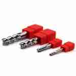
- 2-Flute Square End Mills (AUR) — high helix, open flute design for maximum chip evacuation in aluminum roughing; suitable for slotting, pocketing, and profiling on 6061/7075
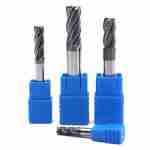
- 4-Flute Square End Mills (NCG / NCP) — balanced edge strength and chip clearance for steel roughing and shoulder milling up to HRC 55; see 4-flute flat end mill specifications
- Corner Radius End Mills (NCP) — reduces stress concentration versus sharp-corner tools; recommended for pre-hardened mold steel roughing (NAK80, P20) where corner breakout is a recurring issue
- Long-Reach Roughing End Mills — for deep-cavity rib and pocket roughing; see our lDie Mold End Mills: A Practical Selection Guide for HRC50–68 Mold Finishing for setup recommendations on extended overhang
- Custom Roughing Geometry — non-standard flute count, chip-breaker groove pattern, or shank to drawing; typical lead time 10–18 working days depending on complexity and quantity — confirm at order placement
Shell end mill note: Shell end mills (arbor-mounted face mills for large-area roughing on horizontal machining centers) are a separate product category from solid carbide roughing end mills. If you are looking for large-face roughing on an HMC, contact our team with your machine spindle spec and workpiece dimensions.
Indicative Cutting Parameters by Material
The following parameters are from JYC Carbide internal tests conducted under controlled conditions: VMC with rigid workholding, coolant as noted, spindle runout verified at ≤ 0.008 mm TIR before each test. Results vary by machine condition, fixture rigidity, depth of cut, and coolant delivery. Use these as a starting point; verify on your actual setup and adjust incrementally.
Aluminum Roughing — AU Series Reference Data
The following data references the AU series (P11, catalog test). AUR roughing-specific parameters follow the same material principles with geometry optimized for higher MRR — confirm AUR parameters at RFQ stage.
| Parameter | AU-3E-D6.0 on LC4 Aluminum | AU-3E-D8.0 on Aluminum HB110 |
|---|---|---|
| Spindle speed n | 13,000 RPM | 13,000 RPM |
| Cutting speed Vc | 250 m/min | — |
| Table feed | 1,950 mm/min | 900 mm/min |
| Feed per tooth fz | 0.15 mm/tooth | — |
| Axial depth ap | 9.0 mm | 8.0 mm |
| Radial depth ae | 1.0 mm | 0.5 mm |
| Coolant | Air cooling | Emulsion |
Steel Roughing — NCG Series (Side Milling, Ø6mm)
| Material | Vc | fz | ap (max) |
|---|---|---|---|
| Carbon / alloy steel ≤ HRC 35 | 200 m/min | 0.24 mm/tooth | 6 mm |
| Stainless steel | 120 m/min | 0.15 mm/tooth | — |
| Pre-hardened steel ≤ HRC 45 | 80 m/min | 0.12 mm/tooth | — |
Pre-Hardened Steel Roughing — NCP Series (Ø6mm, Catalog P9)
| Material | Vc | fz | ap |
|---|---|---|---|
| NAK80 HRC 40 (verified test case) | 120 m/min | 0.20 mm/tooth | 6 mm |
| Pre-hardened steel HRC 40–55 | 100 m/min | 0.15 mm/tooth | — |
All values are side milling (peripheral milling) references. For slotting, reduce spindle speed by 30–50% and feed by 40–60%. Contact engineering for your specific diameter, overhang, and machine setup — parameters scale with tool diameter and machine rigidity.
Precision Tolerances — Standard Production Spec
All JYC Carbide roughing end mills are ground and verified on ZOLLER tool pre-setters and CMM at 20 °C to the following tolerances:
| Dimension | Tolerance | Standard |
|---|---|---|
| Cutting diameter D ≤ 12 mm | 0 – 0.020 mm | DIN 6527 |
| Cutting diameter D > 12 mm | 0 – 0.030 mm | DIN 6527 |
| Corner radius R | ±0.01 mm | JYC internal spec |
| Shank diameter | h6 | ISO 286-1 |
| Runout (TIR) at cutting edge, D ≤ 12 mm | ≤ 0.05 mm | DIN 6527 |
Cutting diameter tolerance is unilateral negative (0 to −0.020 mm for D ≤ 12 mm), meaning the actual diameter is at or below nominal — never above. This prevents interference fits and maintains expected radial engagement. Runout ≤ 0.05 mm is an outgoing inspection sampling standard, not a per-piece guarantee. For tighter tolerance requirements, specify at RFQ for engineering review.
Field Experience: Three Roughing Failure Scenarios
Scenario 1 — BUE on Aluminum Roughing (AUR Fix)
What happens: A 4-flute end mill at moderate feed traps chips between flutes. Aluminum adheres to the cutting face due to chemical affinity between aluminum and cobalt binder. The built-up edge grows with each pass, degrades dimensional control, and ultimately causes unpredictable tool failure.
What works: Switch to AUR-series 2-flute with DLC or uncoated substrate. Use Vc ≥ 200 m/min with air blast or continuous emulsion coolant (not intermittent flood). The larger chip pocket evacuates material before re-cutting. BUE is significantly reduced in most aluminum cavity roughing setups we have supported — verify on your specific machine before full production.
Scenario 2 — Edge Chipping on Pre-Hardened Steel (NCP Fix)
What happens: Using NCG (general steel) geometry on NAK80 HRC 40+ causes micro-chipping at the cutting edge within the first few passes. The substrate lacks sufficient hardness-toughness balance for the harder material. Tool life is unpredictable and often ends in sudden breakage rather than gradual wear.
What works: NCP series, AlTiN coating (~3,300 HV). Maintain fz ≥ 0.15 mm/tooth to avoid rubbing — slowing feed below this threshold on pre-hardened steel accelerates work hardening at the cut zone. For die and mold roughing applications, confirm machine spindle runout ≤ 0.08mm before starting.
Scenario 3 — Chatter and Overload on Deep-Pocket Roughing (Overhang Fix)
What happens: Standard-length roughing end mills used in deep cavities with L/D > 4 generate chatter that degrades surface condition and accelerates tool wear. Operators typically respond by reducing feed further, which worsens the stability problem.
What works: Reduce spindle speed and feed to 90% of catalog values when L/D exceeds 4. For consistent deep-cavity roughing beyond 4×D, switch to an extended-neck configuration with a reduced-diameter neck — see our long-reach end mill guide for parameter recommendations at up to 30×D overhang.
Roughing-to-Finishing Workflow
Step 1 — Define Material, Hardness, and Stock Allowance
Confirm material grade (e.g., 6061-T6, 42CrMo4 at HRC 35, NAK80 at HRC 40) and available stock per side. For automotive part machining with mixed aluminum and steel components in the same fixture, specify each operation separately. Typical stock allowance for finishing:
- Aluminum: leave 0.2–0.5 mm for finishing pass
- Steel / pre-hardened steel: leave 0.1–0.3 mm for finishing pass
Step 2 — Select Roughing Series and Geometry
Use the series table above. Confirm flute count (2-flute for aluminum; 4-flute for steel), corner geometry (square for open pockets; corner radius for mold cavities), and coating. For general machining shop applications with varied steel grades, the NCG series covers ISO P and K materials up to HRC 45 without series switching.
Step 3 — Submit RFQ for Parameter Confirmation
Send: material grade, tool diameter, spindle max rpm, overhang length, machine type (VMC / HMC / 5-axis), and coolant availability. JYC engineers return starting Vc, fz, ap, and ae — response time varies by inquiry volume.
- Standard stocked SKUs: typically ship within 1–7working days of order confirmation (subject to stock at time of order)
- Custom roughing tools: typically 10–30 working days depending on geometry and quantity — confirm at order placement
Manufacturing & Quality Infrastructure
JYC Carbide’s factory with a 270,000 m² integrated production facility. The full manufacturing chain — from tungsten carbide powder through finished cutting tools — is managed in-house: WO₃ → W powder → WC powder → pressed blanks → sintered carbide → precision grinding → finished tools.
Grinding Equipment
- WALTER Helitronic Power 5-axis CNC tool grinding
- ANCA MX7 and FX7 5-axis grinding centers
- ROLLOMATIC NP6X precision step-tool grinding
Measurement & Inspection
- ZOLLER VENTURION tool measurement systems
- Laser OD gauge — in-process diameter verification
- FEI scanning electron microscope (SEM) — edge and coating analysis
- CMM — complex geometry and positional tolerance verification
Certifications
- ISO 9001:2015 — Quality Management
- ISO 14001:2015 — Environmental Management
- ISO 45001:2018 — Occupational Health & Safety
- ISO 50001:2018 — Energy Management
Output & Reach
- 5,000+ standard SKUs
- 1,200+ active customers across 40+ countries
- 40 million+ pieces delivered
For full factory documentation, visit the JYC Carbide manufacturing capability page.
Frequently Asked Questions
What is the difference between a roughing end mill and a finishing end mill?
A roughing end mill removes bulk material fast with high ap and ae, accepting more tool wear per pass. A finishing end mill achieves final dimensions and Ra. Rough first, then finish to tolerance.
When should I use a roughing end mill?
Use a roughing end mill when stock exceeds 1 mm per side, cycle time is the priority, or finishing passes are wearing out too fast. Switch to a finishing end mill for final dimensions and surface finish.
Why do roughing end mills have serrations in the teeth?
Serrations (chip-breaker grooves) split wide chips into smaller segments, reducing cutting forces and heat. This allows higher feed rates and deeper cuts without deflection or chip packing in the flutes.
Ready to Select the Right Roughing End Mill for Your Setup?
Tell us your material grade, tool diameter, spindle max rpm, overhang length, and operation type (pocket roughing / shoulder milling / slotting). Our engineers will recommend the appropriate series and provide starting Vc, fz, ap, and ae values based on your actual conditions.
We provide engineering input — not just a catalog price.
We will suggest the right series for your specific workpiece conditions.
All parameters are starting-point references for trial cutting. Final performance depends on your specific machine, fixture, and operating conditions. JYC Carbide engineers are available to support parameter optimization after trial runs.



Request a Quote for Carbide Tools