ISO 13399 cutting tool data is an international framework for representing and exchanging cutting tool information in a computer-readable form, independent of any single CAD, CAM, or ERP system. ISO 13399:2006 defines the main categories of cutting tool data and the relationships between them, giving suppliers and buyers a shared structure instead of a proprietary spreadsheet or PDF layout.
It was built to sit behind digital catalogs, tool-management software, and PLM systems, not to replace the drawing or the RFQ. For a distributor, this matters at the point where a supplier’s catalog data has to become usable rows inside a customer’s tool room database.

Which Tool Properties It Covers
The standard organizes cutting tool information into linked categories: general item identification, geometric data, technological data such as coating and cutting parameters, and administrative data such as supplier and packaging information. The actual diameter, tolerance, or coating on a given part still comes from the carbide manufacturer‘s own specification, not from the standard.
This distinction matters for accuracy: ISO 13399 tells a system where a diameter field belongs in the data structure. It does not tell you what the diameter is for a given tool family.
ISO 13399 Against a PDF Catalog
A PDF catalog and an ISO 13399-structured data file describe the same tool, but only one can be read directly by software. The practical difference shows up in field consistency, machine readability, and update handling.
Neither format is inherently more accurate — the difference is how much manual work sits between the supplier’s number and the system that needs it. This is one reason buyers increasingly check a supplier’s carbide standards and specifications documentation before assuming a data file is import-ready.
Why Distributors and CAM Users Ask for Structured Data
Catalog data keyed into a CAM system by hand risks a tool crash from a mistyped parameter — a diameter or overall length copied incorrectly from a PDF table does not show up as an error until the tool is already in the spindle.
How to Check a Supplier Tool Data File
Confirm the file lists the fields your system expects, confirm whether 2D or 3D geometry is included, and cross-check one or two values against the supplier’s own product page before importing. This kind of cross-check is part of a broader process to evaluate a carbide tool supplier before committing a data file to production use.
Data We Can Deliver Per Tool
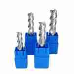
For carbide end mills produced to standard catalog sizes, the deliverable field set covers model code, cutting diameter, shank diameter, cutting length, overall length, flute count, coating, helix angle, radius, neck length, material suitability, and starting cutting parameters.
Field List for One End Mill Record
| Field | Example Value | Deliverable |
|---|---|---|
| Model code | TVR-NCG-4E-D6.0 | Yes |
| Cutting diameter | 6.0 mm | Yes |
| Shank diameter | 6 mm | Yes |
| Cutting length | 16 mm | Yes |
| Overall length | 50 mm | Yes |
| Flute count | 4 | Yes |
| Coating | TiAlN | Yes |
| Helix angle | 45° | Yes |
| Diameter tolerance | 0 / −0.020 mm | Yes |
| Formal ISO 13399 attribute codes | Not mapped | Available on request |
Requesting a Data Package
A data request is more useful when it specifies the exact field list, the file format, the range of tool families covered, and the update frequency. Manufactured to customer drawing for non-standard geometries — this applies equally to custom carbide tools built outside the standard catalog range, where a data record has to be generated per drawing rather than pulled from an existing table.
FAQ
What product data is included in ISO 13399?
The standard covers linked categories of cutting tool data — general identification, geometric data, technological data such as coating, and administrative data such as supplier details. It defines where each type of information sits in the structure; the actual values for a given tool come from the manufacturer’s specification, not from the standard itself.
Is ISO 13399 required for custom carbide tools?
No. The standard is a voluntary data-representation framework and does not restrict which tool types or materials it can describe. A custom carbide tool can be documented with the same field structure as a catalog item once its dimensions are confirmed on a drawing.
How does it help CAM and tool-management systems?
By giving every tool record the same field structure, it reduces the manual retyping step between a supplier’s catalog and a CAM or PIM system, which is where transcription errors most often enter a tool database.
Can 2D drawings and 3D models be exchanged?
Data packages built around this framework can reference 2D drawings and 3D models alongside the numeric fields, but not every supplier export includes geometry files by default. Confirm this coverage before assuming a file includes them.
What data should a distributor request from a tool factory?
At minimum: the exact field list the distributor’s own system needs, the file format it can import, which tool families are covered, and how often the data will be updated as new sizes are released.



Request a Quote for Carbide Tools