An ISO 1832 indexable insert designation code provides a standardized alphanumeric framework for describing the core physical geometry, mounting features, and reference dimensions of indexable cutting inserts. For procurement engineers and tooling specifiers, misunderstanding these character positions on an engineering drawing or supplier quotation can result in purchasing inserts with incompatible clearance angles, incorrect mounting clamping styles, or mismatched corner radii.
The primary procurement objective when reviewing an ISO 1832 code is to confirm that each position—from insert shape and clearance angle to tolerance class, clamping type, insert size, thickness, and corner radius—matches your toolholder pocket and operational requirements before issuing a purchase order or request for quote (RFQ).

What Is the Scope and Purpose of ISO 1832?
ISO 1832 establishes a standardized designation system for indexable inserts made of hard cutting materials, defining reference geometry, dimensions, and edge preparations so that cutting tools can be systematically identified across manufacturers.
Using standardized ISO designations enables buyers to communicate physical geometry and toolholder compatibility clearly across international tooling suppliers.
The official scope published by the International Organization for Standardization (ISO 1832) covers indexable inserts manufactured from hard cutting materials, including cemented carbide, ceramic, cubic boron nitride (CBN), and polycrystalline diamond (PCD).
Verify whether your internal part drawings and supplier line items use the standardized ISO 1832 code format rather than proprietary vendor abbreviations before approving tooling orders.
According to the official ISO 1832 standard scope, the system applies broadly across multiple cutting materials. It is not limited strictly to tungsten carbide; it also establishes identification principles for high-performance superabrasives such as CBN, PCD, and ceramic materials. This ensures that the fundamental geometry of the insert pocket and cutting profile remains universally interpretable across different substrate categories.
While ISO 1832 standardizes the geometric identification system, buyers should recognize that specific dimensional details, tolerance limits, and edge conditions must be cross-referenced against the official standard text or the supplier’s technical catalog drawings.
Decision checkpoint
- Confirm that your requisition records the full ISO alphanumeric designation rather than an abbreviated or vendor-specific shorthand.
- Check whether the required tool material is cemented carbide, CBN, PCD, or ceramic, as ISO 1832 covers these hard cutting material categories.
How to Read ISO 1832 Insert Codes: Position Breakdown
An ISO 1832 insert code uses a sequential structure where the first four letters define insert shape, major clearance angle, tolerance class, and clamping/chipbreaker configuration, followed by numeric positions for insert size, thickness, and corner radius.
Misinterpreting a single character—such as confusing a 7-degree positive clearance (C) with a negative insert (N)—results in immediate toolholder collision or inadequate cutting clearance.
Standard industry tooling catalogs and engineering consensus follow a consistent position map corresponding to the ISO 1832 designation architecture.
Match each character in designations like CNMG or CCMT against the corresponding geometric feature position before submitting drawing specifications.
In typical industry catalog practice based on the ISO framework, standard turning and milling inserts are identified by a sequence of positions. The breakdown below reflects the established industry implementation consensus for standard 7-position turning inserts, such as the widely used CNMG or CCMT formats.
Please note: While the functional positions below reflect widespread cutting tool manufacturing consensus, precise numerical tables and edge condition modifiers should always be confirmed via the supplier’s technical data sheets or the complete ISO 1832 standard text.
Standard 7-Position Framework Overview
The standard sequence follows seven primary geometric designations:
- Position 1 (Insert Shape Code): Identifies the insert geometry (e.g., C for 80° rhombic, W for trigon, T for triangular, S for square, D for 55° rhombic, V for 35° rhombic, R for round).
- Position 2 (Clearance Angle Code): Identifies the primary relief/clearance angle (e.g., N for 0° negative insert, C for 7° positive clearance, P for 11° positive clearance).
- Position 3 (Tolerance Class Code): Defines the precision class for inscribed circle, thickness, and nose height (e.g., M for standard molded/utility tolerances, G for precision ground tolerances).
- Position 4 (Clamping & Chipbreaker Style): Identifies hole features, countersink angle, and whether chipbreakers are present on one or both faces (e.g., G for cylindrical hole with double-sided chip grooves, T for countersunk hole with single-sided chip groove).
- Position 5 (Insert Size / Inscribed Circle): A two-digit numeric code designating the length of the cutting edge or inscribed circle (e.g., 12 for a 12.7 mm inscribed circle).
- Position 6 (Insert Thickness): A two-digit numeric code specifying the insert thickness (e.g., 04 for 4.76 mm nominal thickness).
- Position 7 (Corner Radius): A two-digit numeric code specifying the nominal nose radius (e.g., 08 for 0.8 mm corner radius, 04 for 0.4 mm corner radius).
| Position | Geometric Property | CNMG 120408 Meaning | CCMT 09T304 Meaning |
|---|---|---|---|
| 1 | Shape | C (80° Rhombic) | C (80° Rhombic) |
| 2 | Clearance Angle | N (0° Negative rake) | C (7° Positive clearance) |
| 3 | Tolerance Class | M (Molded / Utility) | M (Molded / Utility) |
| 4 | Hole / Clamping | G (Hole + Chipbreakers both faces) | T (Countersunk hole + Single-sided) |
| 5 | Insert Size | 12 (12.7 mm nominal edge) | 09 (9.525 mm nominal edge) |
| 6 | Thickness | 04 (4.76 mm nominal thickness) | T3 (3.97 mm nominal thickness) |
| 7 | Corner Radius | 08 (0.8 mm nose radius) | 04 (0.4 mm nose radius) |
Decision checkpoint
- Confirm that Position 2 matches your toolholder pocket: a negative insert (N) cannot seat correctly in a pocket engineered for a positive clearance insert (C or P).
- Ensure Position 7 (Corner Radius) aligns with your finished component corner radius drawing constraints.
Does ISO 1832 Specify Carbide Grade or Coating Information?
No, the ISO 1832 designation code standardizes physical shape, clearance, tolerance class, and dimensional geometry, but it does not specify the proprietary substrate carbide grade, chemical composition, or PVD/CVD coating layer.
Procurement teams cannot rely solely on the ISO 1832 code to ensure material compatibility; specifying only ‘CNMG 120408’ leaves the tungsten carbide grain structure, binder content, and coating type entirely undefined.
Official ISO 1832 standard documentation focuses on dimensional and geometric designation; manufacturers append proprietary suffixes or grade codes to designate substrate grades and coating types.
Always pair the ISO 1832 designation with the exact workpiece material, application group (ISO P, M, K, N, S, H), and supplier-specific carbide grade recommendation in your RFQ.
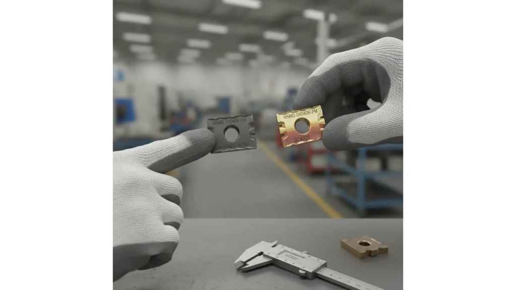
A frequent procurement misconception is assuming that two inserts sharing identical ISO 1832 codes (e.g., WNMG 080408-PM) will perform identically across different manufacturers. While their physical dimensions and mounting compatibility will match, their wear resistance, fracture toughness, and thermal stability are determined by the underlying cemented carbide material and specialized coating systems.
Manufacturers typically add manufacturer-specific suffixes after the 7th or 8th position (such as chipbreaker geometry codes like -PM, -MA, -GH) followed by their proprietary grade names (e.g., CVD TiCN-Al2O3 coated grades for steel turning or uncoated ultra-fine grain grades for non-ferrous applications). When sourcing non standard carbide products or standard indexable tooling, buyers must communicate the application demands alongside the geometric code.
Decision checkpoint
- Specify the exact target ISO material group (e.g., ISO P for carbon steel, ISO M for stainless) alongside the ISO 1832 geometry code.
- Request the supplier’s grade data sheet and coating specification rather than ordering by the 7-character geometry code alone.
Drawing and RFQ Checklist for Indexable Insert Procurement
Before issuing a purchase order or RFQ for indexable tooling, buyers should verify seven geometric positions and provide all necessary workpiece and operational parameters to prevent sourcing errors.
A complete, structured RFQ prevents delivery delays, tooling mismatches, and avoidable rework on production machining lines.
Tooling procurement verification requires cross-checking part print dimensions and toolholder pocket compatibility against supplier quotation lines.
Use the checklist below when drafting technical inquiries or reviewing vendor quotations for indexable inserts.
To ensure complete clarity between your machining requirements and the supplier’s manufacturing capabilities, audit your RFQ documentation against the following verification items before confirming the order.
- Shape Code (Position 1): Verify insert angle (e.g., C=80°, D=55°, T=60°, V=35°, W=Trigon) matches toolholder clearance and component profile accessibility.
- Clearance Angle Code (Position 2): Ensure primary relief (e.g., N=0°, C=7°, B=5°, P=11°) matches toolholder seat rake design.
- Tolerance Class Code (Position 3): Confirm precision requirements (e.g., M for standard roughing/semi-finishing, G/E for high-precision finishing operations).
- Clamping & Chip Groove Style (Position 4): Verify hole geometry (cylindrical, countersunk, or solid) matches the clamp screw, lever, or top-clamp mechanism of your holder.
- Size & Inscribed Circle (Position 5): Confirm nominal cutting edge length corresponds to required depth of cut and holder pocket size.
- Thickness Code (Position 6): Check insert thickness against pocket seating depth to prevent mechanical overhang or clamping instability.
- Corner Radius (Position 7): Validate nose radius against component fillet radius tolerances and surface finish targets.
- Workpiece Material & Hardness: Specify alloy grade, condition, and hardness (HRC/HB) to select appropriate carbide substrate and coating.
- Operation & Machine Setup: State whether the application involves continuous turning, interrupted facing, heavy roughing, or fine profiling, along with machine stability.
Decision checkpoint
- Review vendor quotation line items character-by-character against this checklist prior to issuing final purchase orders.
- Request dimensioned product drawings from the supplier if custom edge preparations or non-standard tolerances are required.
Frequently Asked Questions
What is the primary difference between ISO 1832 and manufacturer-specific insert codes?
ISO 1832 establishes the standardized global system for insert geometry, clearance, tolerance class, and nominal dimensions. Manufacturer-specific codes typically append proprietary chipbreaker designations and substrate grade names to identify specific coating technologies and material applications.
What do the letters in common turning inserts like CNMG mean?
Under standard industry practice following the ISO framework, ‘C’ designates an 80-degree rhombic shape, ‘N’ represents a 0-degree negative clearance angle, ‘M’ indicates standard manufacturing tolerance class, and ‘G’ specifies a cylindrical center hole with chipbreaker grooves on both top and bottom faces.
Does ISO 1832 apply to superhard tool materials like PCD and CBN?
Yes. The official scope of ISO 1832 covers indexable inserts made of hard cutting materials, which include cemented carbide, ceramic, polycrystalline diamond (PCD), and cubic boron nitride (CBN).
Where can exact tolerance dimensions for insert tolerance classes (such as Class M or Class G) be verified?
Exact numerical tolerance limits for inscribed circle, thickness, and nose height are specified in the official ISO 1832 standard documentation and detailed technical product catalogs provided by cutting tool manufacturers.
Discuss Your Tooling Requirement
Send the workpiece material, hardness, operation, tool diameter, reach, machine and holder details for a bounded tooling review.
Send your machining requirements to TUNGVARA.