Carbide Tool Supplier Guide
This guide is written for CNC engineers and procurement managers evaluating carbide tool suppliers for aluminum, 304/316 stainless steel, and engineering plastics. It covers what to verify — geometry, coating match, precision specifications, and process consistency — rather than how any single supplier describes itself.


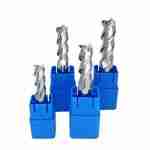
For a direct overview of available product lines, see carbide end mills or the full carbide tool range.
1. What to Verify When Evaluating a Carbide Tool Supplier
Two tools with identical nominal specifications can produce very different results in cutting. The following criteria are worth confirming before placing an order.
Geometry Optimized by Material
General-purpose geometry is acceptable for most steel applications, but aluminum needs wide chip gullets and high helix angles to evacuate chips at high feed rates. Stainless steel needs controlled radial engagement to prevent chatter. Plastics and acrylic require extremely sharp cutting edges to avoid heat buildup and edge melting. Ask suppliers to specify rake and relief angle ranges for each series and the target material group they address.
Coating Matched to Material
- AlTiN / TiAlN: Steel and stainless steel, heat resistance under dry or semi-dry conditions
- AlCrN / nACo: Austenitic stainless steel and superalloys, oxidation resistance and reduced built-up edge (BUE) tendency
- DLC (diamond-like carbon) or polished substrate: Aluminum and non-ferrous materials, prevents chip adhesion
- Uncoated or polished: Engineering plastics and acrylic, preserves edge sharpness
A supplier offering “full range coatings” does not mean each coating is appropriate for each material. Confirm per material group before ordering.
Verifiable Process Consistency
Batch consistency can be confirmed through the following:
- Shipment inspection report
- Spot-check runout TIR: ≤0.05 mm at D ≤12 m
- Diameter tolerance: 0 − 0.020 mm for D ≤12 mm; 0 – 0.030 mm for D >12 mm
Claims of Cpk >1.67 represent a meaningful process capability level (approximately 5-sigma). If this is specified, confirm by requesting historical Cpk records or sample inspection reports at RFQ stage — not solely based on marketing materials.
2. Aluminum Machining: Tool Selection Principles
Aluminum alloys (6061, 7075, A380) tolerate high cutting speeds but are highly sensitive to chip evacuation and BUE. The right tool geometry matters more here than in steel.
Recommended Series
| Series | Application | Key Feature |
|---|---|---|
| AU | Aluminum finishing and side milling | 2–3 flute, helix angle ≥45°, polished or DLC |
| AUR | Aluminum roughing, high material removal rate | Coarser pitch, optimized for high fz |
| O-flute ball nose | High-gloss finishing, thin-wall contours | Single large flute, minimal chip re-cutting |
For aluminum end mill geometry options, see the 2-flute ball end mill for aluminum.
The BUE Problem in Aluminum
Built-up edge is the most common failure mode in aluminum machining. Aluminum chips weld to the cutting edge at lower temperatures than steel, particularly when cutting speed is too low. The solution path: use DLC or polished-substrate tools, run Vc ≥150–200 m/min where spindle allows, ensure adequate coolant delivery, and replace tools before edge wear causes adhesion.
Starting Parameter Reference (Confirm per Workpiece at RFQ)
For 6061-T6, full slot (ae = D), Ø10 mm, 2-flute, polished: Vc approximately 150–250 m/min, fz approximately 0.03–0.06 mm/tooth, ap = 0.5–1×D (start at the low end and validate).
3. Stainless Steel Machining: Tool Selection Principles
The main challenges with 304 and 316 stainless steel are work hardening, high cutting heat concentration, and BUE tendency. Wrong tooling choices result in rapid edge degradation rather than gradual wear.
Recommended Series and Coating
The NCPX stainless steel specific end mill uses unequal pitch and variable helix geometry to reduce vibration tendency. For coating, AlCrN or nACo outperforms TiAlN on austenitic stainless steel by providing better oxidation resistance in the adhesion-prone cutting zone.
Operating Rules That Reduce Failure Rate
- Keep ae ≤ 0.5×D for stainless full-slot starts: Side milling at reduced radial engagement is safer until cutting stability is confirmed
- Never dwell mid-cut: Stopping tool feed while spindle is running work-hardens the surface; the next pass cuts into a hardened zone and chips the edge
- Coolant volume matters: Cutting heat is the primary driver of edge degradation in stainless steel; dry or minimal-coolant setups reduce tool life significantly
A Note on Tool Life Comparison Claims
Any “40% longer tool life in 304 stainless roughing” claim — including from JYC Carbide’s own test data — is only valid when the baseline tool, coating, Vc, fz, and machine setup are specified. Variation between shops, machines, and operators can exceed 200%. Use published data as directional guidance only; validate on your own setup before adjusting production parameters.
4. Engineering Plastics and Acrylic: Tool Selection Principles
Engineering plastics (PTFE, POM, PA66) and acrylic (PMMA) share one fundamental requirement: the cutting edge must be as sharp as possible to cut cleanly rather than deforming the material thermally.
Selection Rules
- Rake angle ≥20°: Reduces cutting force and generates less heat at the edge
- Uncoated or polished substrate over TiAlN: Hard coatings increase edge radius and reduce sharpness; not recommended for plastics unless material compatibility is confirmed
- High rpm, low fz for thin-wall features: Reduces vibration-induced chipping and dimensional distortion
O-Flute Ball Nose for Acrylic Finishing
The O-flute (single large flute) ball nose design reduces chip re-cutting in acrylic — each chip evacuates cleanly rather than passing through the cutting zone a second time. Ra ≤0.4 μm is achievable under the following conditions: spindle runout ≤0.05 mm, stepover ae/ap ≤0.05×D, adequate fixturing rigidity, and a properly conditioned cutting edge. Any of these factors out of range shifts the surface result significantly.
5. JYC Carbide Production and Precision Specifications
Precision Standards
| Parameter | Tolerance | Reference Standard |
|---|---|---|
| Cutting diameter D ≤12 mm | 0 −0.020 mm | — |
| Cutting diameter D >12 mm | 0 −0.030 mm | — |
| Shank tolerance | h6 | ISO 286-1 |
| Runout TIR (D ≤12 mm) | ≤0.05 mm | — |
For shank tolerance definitions (h5 vs h6) and DIN standard references, see the DIN 6537 and DIN 6535-HA standards page.
Manufacturing Infrastructure
- Grinding equipment: P3 WALTER / ANCA / ROLLOMATIC
- Measurement equipment: ZOLLER / Laser / FEI / CMM
- Certifications: ISO 9001 / 14001 / 45001 / 50001 / COC / SGS
- Active customers: 1,200+ across 40+ countries
- Total pieces delivered: 40 million+
- SKUs: 5,000+ standard configurations
Each order ships with a shipment inspection report. SGS third-party reports are available as an optional service — confirm requirement at RFQ stage.
6. Tool Series Quick Reference
| Series | Material Group | Hardness / Condition |
|---|---|---|
| NCG | General steel | HRC≤45 |
| NCP | Pre-hardened steel | HRC≤55 (P20, 718, NAK80) |
| NCPX | Stainless steel | 304, 316, 17-4PH, 1Cr18Ni9Ti |
| NCH | Hardened steel | HRC45–65 (SKD11, D2, H13) |
| NCJ | Small-diameter precision | D1–D6 mm |
| AU | Aluminum finishing | 6061, 7075, A380 |
| AUR | Aluminum roughing | High MRR aluminum applications |
For hardened steel mold cavity applications at HRC45–65, see hardened steel end mills (NCH series). For aerospace aluminum structural parts, see aerospace machining applications.
7. Frequently Asked Questions
How do I confirm a coating is appropriate for my material?
Start with the basic matrix: aluminum → DLC or polished; stainless steel → AlCrN/nACo; steel → AlTiN/TiAlN; plastics → uncoated or polished. Actual coating impact also depends on substrate hardness, edge preparation, and coolant method. Confirm per specific workpiece conditions at RFQ stage.
What does Cpk >1.67 mean in practice?
Cpk is a process capability index. A value of 1.67 corresponds to approximately 5-sigma process control, meaning critical dimensions (such as cutting diameter) are distributed within one-fifth of the tolerance band. Verify by requesting a sample inspection report — not solely based on marketing claims.
What information do I need to request an O-flute ball nose end mill?
Provide cutting diameter, overall length, shank diameter, target material (aluminum grade or plastic type), target surface finish Ra, spindle maximum rpm, and workpiece fixturing method. An O-flute is not recommended for steel or high depth-of-cut roughing applications — confirm application suitability at RFQ stage.
8. What to Confirm Before RFQ
- Workpiece material grade and actual hardness or heat treatment condition
- Machining operation: full slot, side milling, 3D contouring, or finishing
- Required cutting diameter, flute count, overall length, and stickout
- Machine type, maximum spindle speed, holder system, and coolant method
- Current issue: BUE, burring, dimensional drift, surface finish not meeting drawing
- Volume requirement and whether non-standard specifications are needed
9. Request a Specification
Tool selection should be based on workpiece material, machining operation, and verifiable specifications — not on supplier self-description. Submit your material, hardness, operation type, machine setup, and current tooling issue. JYC Carbide will provide a series recommendation, starting parameter range, and shipment inspection report based on your RFQ.
We will provide application-specific recommendations based on your actual machining conditions. Sample policy, lead time, and non-standard requests are confirmed during inquiry.



Request a Quote for Carbide Tools