Author: Senior CNC tooling engineer Reviewed by: Process engineer, JYC Carbide Last updated: May 2026
Metal Cutting Tools: Practical Basics from Materials to Applications
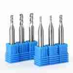
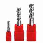
In modern CNC machining, metal cutting tools covers end mills, drills, turning tools, reamers, taps, and more, all used to remove material and create specific part features. Whether you run a mold shop, an automotive supplier, or a general job shop, real results rarely come from a single “magic” tool. They come from how the tool substrate, coating, and geometry work together with your machines, fixturing, and cutting parameters; if you need a quick overview of common tool families, the catalog for solid carbide end mills and related milling cutters is a useful reference when you plan your roughing and finishing strategies.


Typical Part Features for Metal Cutting Tools
Common features in daily machining
With reasonable tool selection, metal cutting tools can cover most common features on metal parts, for example:
- External profiles, faces, steps, angles, and basic contours.
- Holemaking: drilling, enlarging, reaming, tapping, and fine boring.
- Cavities, narrow slots, thin walls, ribs, and bosses.
- Functional surfaces such as precision fit faces, seal grooves, and guideways.
- Complex 3D surfaces such as impellers, turbine blades, and mold cavities.
- Chamfers, deburring, markings, and light engraving as secondary operations.
It is important to state clearly: there is no single tool that handles every feature with no compromise. Each feature type usually has tool families that are better suited for it, for example: long‑neck or reduced‑neck tools for deep cavities, and light‑cutting geometries for thin‑wall work; the application pages for general machining jobs can help you compare typical part features with your own work.
Common Material Groups for Metal Cutting Tools
Typical metals and alloys
Different materials place very different demands on tool substrate and coating. Typical material groups for modern metal cutting tools include:
- Carbon steels, alloy steels, and mold steels (for example P20, 1.2738, NAK80, S136, SKD11, H13).
- Stainless steels (for example 303, 304, 316L, 420, 440C, 17‑4PH).
- Pre‑hardened and hardened steels, often in the HRC30–60 range.
- Aluminum and aluminum alloys (for example 6061, 7075, 5083).
- Titanium alloys such as Ti6Al4V / TC4.
- High‑temperature alloys such as Inconel 718 and Hastelloy grades.
- Copper, brass, bronze, and high‑conductivity copper.
- Cast iron, ductile iron, and wear‑resistant cast materials.
- Selected engineering plastics and composites (such as CFRP) with dedicated geometries.
In practice, most shops use ISO P/M/K/S/N/H material groupings to choose more specialized tools, instead of relying on a “universal” design. For hardened steels, high‑temperature alloys, or composite materials, it is worth discussing the application with a tooling engineer before ordering, so they can suggest a more suitable series and coating approach; for example, the notes in the machining hardened steel guide offer practical context for tool choice in higher HRC ranges.
From Stock to Finished Part: Tool Roles at Each Stage
Roughing, semi‑finishing, and finishing
A metal part usually passes through several machining stages from raw stock to finished component. Each stage tends to use different cutting tools and strategies:
- Roughing – focus on metal removal rate and security. Typical choice: stiffer tools with higher flute count and stronger edges, with larger ap and ae to move material efficiently.
- Semi‑finishing – focus on getting close to size and improving surface finish while leaving a small allowance. Typical choice: tools with variable helix or unequal pitch to improve stability and reduce chatter.
- Finishing – focus on dimensional tolerance and form accuracy. Typical choice: light‑cutting tools, smaller step‑over and feed, and controlled edge prep to achieve the required tolerance and surface roughness.
- Pre‑polish or pre‑grind passes – when necessary, use ball nose or corner‑radius tools to create consistent stock for subsequent grinding or polishing on critical surfaces.
- Chamfering, deburring, and engraving – often handled by dedicated chamfer tools, combined drill‑chamfer tools, or small engraving cutters as a separate operation.
In practice, it is usually a bad idea to expect one tool to run from heavy roughing all the way through final finishing. A more robust approach is to assign metal cutting tools to roughing, semi‑finishing, and finishing according to feature importance, tolerance levels, machine rigidity, and production volume, then refine the parameters through trial cuts; if you want a deeper dive into tool families by operation, the cutting tools insights hub is a good place to explore more detailed examples.
Substrate, Coating, and Geometry: Typical Design Directions
Balancing hardness, wear, and stability
Modern cemented carbide cutting tools need a balanced design across several dimensions:
- Substrate hardness and toughness – fine‑grain or ultra‑fine‑grain carbide can offer high hardness while maintaining reasonable toughness. Hardened steels often require higher hot hardness and edge stability to avoid chipping.
- Coating type and performance – steels commonly use PVD coatings such as AlTiN or AlCrN to improve wear and heat resistance. Stainless steels and high‑temperature alloys are more sensitive to notch wear and built‑up edge (BUE), so they often require specialized coatings and edge prep. Aluminum alloys benefit from polished flutes and coatings or surface treatments that reduce built‑up edge and improve chip evacuation.
- Geometry and edge preparation – variable helix and unequal pitch can reduce vibration and improve surface finish in many setups. Thin‑wall parts and long overhangs depend heavily on helix angle, core thickness, and edge hone to control deflection and chatter.
- Tool construction – long‑neck and reduced‑neck tools help in deep cavity and step transitions. Through‑coolant drills support chip evacuation and cooling in deep‑hole work. In some applications, indexable tools or replaceable‑head systems can help reduce change cost and downtime.
The effect of each design choice depends on machine rigidity, workholding, coolant delivery, and the selected combination of Vc, fz, ap, and ae. Because of this, it is more accurate to talk about “better stability in a given setup” than to promise universal “multiple‑X tool life” or “no tool breakage”; for more background on geometries and dimensions, the milling cutters and metric end mill guides offer additional reference points.
How to Validate a Metal Cutting Tool Plan in Production
A simple validation workflow
Whether you are evaluating a standard tool or a custom design, it is helpful to follow a structured validation process:
- Basic incoming check – inspect the tools for visual defects, edge condition, and correct shank dimensions. Run a simple TIR check in the toolholder when tight tolerances are required.
- Start with conservative parameters – begin with moderate cutting speed (Vc), feed per tooth (fz), and depths of cut (ap, ae). Observe tool wear patterns, chip formation, and surface finish before pushing harder.
- Link to drawing requirements – for critical dimensions and surfaces, align tool choice and parameters with drawing tolerances and roughness requirements (for example Ra/Rz). Adjust step‑over, step‑down, and toolpath strategies based on how the part responds.
- Use small trial batches – for new materials, new tools, or new machines, validate performance on a small number of parts before committing to large‑volume orders.
Before you start testing, it usually helps to share details with your tooling supplier: material grade and hardness, machine model, holder type, coolant condition, and target tool life or number of parts per edge. This allows the supplier to offer parameter ranges that are more realistic for your situation instead of generic catalog values; if you want to compare your approach with other shops, the machining articles in the carbide technical hub provide additional practical insights.
When You Should Involve a Tooling Engineer
Situations where expert input pays off
In some situations, involving a tooling engineer early saves significant time and scrap:
- New materials, new mold steels, or higher hardness ranges entering production.
- Deep cavities, long slender shafts, thin‑wall parts, or other geometry very sensitive to vibration.
- Critical mold parting lines, mirror‑finish areas, and seal surfaces.
- Cases where existing tools show frequent chipping, severe chatter marks, or highly inconsistent tool life.
You can share drawings, material specifications, and a short description of your current setup so an engineer can review them and suggest metal cutting tools families and starting parameters. Any specific expectations around tool life, cycle‑time reduction, or cost savings should always be evaluated with real cuts and data, not treated as a fixed promise. If you are ready to start that conversation, the contact page for RFQ and technical questions is a straightforward way to send your information and request tooling suggestions that take your machining conditions into account.
Send your RFQ with materials and cutting conditions
We will review your part drawings, materials, and machine setup and provide tool suggestions tailored to your machining conditions, not a one‑size‑fits‑all offer.
FAQ
What are the main types of metal cutting tools in CNC machining?
Common tools include end mills, drills, taps, reamers, turning inserts, and boring tools, each selected by operation, material, and required accuracy.
Why does tool geometry matter so much in metal cutting?
Helix angle, flute count, and edge prep control chip flow, cutting forces, chatter risk, and achievable surface finish on each part feature
How do I choose metal cutting tools for a new material?
Start from the ISO P/M/K/S/N/H group, then match substrate, coating, and geometry to hardness, coolant condition, and your machine’s rigidity.
About This Article
This guide is written from a practical machining and sourcing perspective to help CNC shops use metal cutting tools more confidently. It is reviewed periodically to reflect current material mixes, shop practices, and feedback from machinists, process engineers, and purchasing teams.



Request a Quote for Carbide Tools