Solid Carbide End Mills for Aluminum, Stainless & Plastics
By JYC Carbide Application Engineering Team | Last reviewed: April 2026
Running the wrong end mill geometry or coating for your material is one of the most direct causes of built-up edge (BUE) on aluminum, work hardening on 304 stainless, and melt-fray on acrylic — all of which shorten tool life and degrade part finish before the job is done. JYC Carbide manufactures seven material-specific solid carbide end mill series on WALTER, ANCA, and ROLLOMATIC 5-axis CNC grinding systems, with every batch measured on ZOLLER tool pre-setters and CMM.


This page covers: series selection by material, performance data with stated test conditions, dimensional tolerances per DIN 6527 and ISO 286-1, and how to request a starting parameter set for your exact setup.
Why End Mill Mismatch Costs More Than the Tool
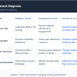
One of the most common issues our application engineers encounter: a customer running a 4-flute, TiAlN-coated end mill on 6061-T6 aluminum at standard feed and speed. Within the first few passes, aluminum begins welding to the cutting flutes — a textbook built-up edge (BUE) condition. Surface finish deteriorates, dimensional accuracy drifts, and the tool fails well before its rated life. The fix — switching to a single O-flute AU-series end mill with DLC or uncoated geometry at Vc ≥ 200 m/min with air-blast coolant — resolves BUE in most aluminum cavity applications. But the lost machine hours are not recoverable.
On 304 stainless, the failure mode is different. A low-helix end mill (< 30°) with insufficient coating hardness generates heat at the shear zone faster than chips carry it away. The workpiece work-hardens ahead of the cut, micro-chipping appears on the flank, and tool life becomes unpredictable. The most frequent operator mistake: slowing the feed rate when chatter starts, which makes work hardening worse. Maintaining fz above 0.025 mm/tooth keeps the tool cutting rather than rubbing.
Understanding your specific failure mode — not just the material — is the starting point for selecting the right series. For a broader overview of tool selection across materials, see our carbide end mill selection guide.
Product Series: Material-Based Selection
JYC Carbide solid carbide end mills are grouped into seven series. Each uses a substrate grade and geometry optimized for the target material family.
| Series | Target Material | Hardness Range | Typical Coating | Common Failure Avoided |
|---|---|---|---|---|
| NCG | General steel, cast iron (ISO P/K) | ≤ HRC 45 | TiAlN (~3,200 HV) | Flank wear in interrupted cuts |
| NCP | Pre-hardened steel: NAK80, P20 | ≤ HRC 55 | AlTiN (~3,300 HV) | Edge chipping on pre-hard |
| NCPX | Stainless steel: 304, 1Cr18Ni9Ti | — | TiAlN / AlTiN | Work hardening, BUE |
| NCH | Hardened tool steel: SKD11, D2, H13 | HRC 45–65 | TiSiN / nano-composite | Thermal cracking, micro-chipping |
| NCJ | Small-diameter precision milling | D1–D6 mm | TiAlN or uncoated | Deflection, runout sensitivity |
| AU | Aluminum & non-ferrous (finishing) | — | DLC or uncoated | BUE, poor surface finish |
| AUR | Aluminum roughing (high MRR) | — | DLC or uncoated | Chip packing, re-cutting |
Application note — NCH series (HRC 45–65): Above HRC 62, confirm spindle runout ≤ 0.010 mm TIR and overhang L/D ≤ 3 before ordering. For setups outside these parameters, contact our engineers before selecting tooling.
Application note — NCPX (stainless): Higher helix angles (35–45°) reduce cutting forces and heat generation. Confirm minimum fz ≥ 0.025 mm/tooth to avoid rubbing-induced work hardening.
Featured Tool Types
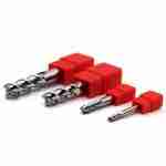
JYC Carbide’s end mill range covers 5,000+ standard SKUs across the following types:
- Square End Mills — 2–6 flutes; suitable for slotting, shouldering, and profiling on NCG / NCP / NCPX series materials
- Ball Nose End Mills — optimized for 3D contouring on die and mold surfaces; NCJ (D1–D6 mm) and NCH configurations available; see our die & mold machining applications for context
- O-Flute Ball Nose End Mills — single-flute design for mirror-finish aluminum and acrylic (AU series); maximizes chip evacuation, eliminates BUE in most non-ferrous finishing setups
- Corner Radius End Mills — reduces stress concentration versus sharp-corner tools; recommended for NCP series on pre-hardened molds
- Long-Reach / Extended-Neck End Mills — for deep-cavity rib and pocket work; see our Long Flute Flat End Mills For Stainless Steel
- 4-Flute Straight-Shank Flat End Mills — general-purpose profiling and shoulder milling; see 4-flute flat end mill specifications
- Carbide Reamers — final-pass bore finishing on steel and aluminum to IT6–IT7 tolerances; see carbide reamer range
- Custom Tooling — geometry, flute count, corner radius, coating, and shank to your drawing; typical lead time 10–18 working days (subject to order complexity; confirm at order placement)
For high-volume precision hole applications, carbide drills with coolant-through options are available alongside the end mill range.
Indicative Performance Data by Material
The following data is from JYC Carbide internal comparative tests conducted under controlled conditions: VMC with flood or air-blast coolant as noted, rigid workholding, spindle runout verified at ≤ 0.08 mm TIR before each test. Results vary by machine condition, fixture rigidity, depth of cut, and coolant type. Use these as starting-point references; verify on your specific setup and adjust accordingly.
| Parameter | 6061/7075 Aluminum — AU series, O-flute DLC | 304 Stainless — NCPX, 4-flute AlTiN | Plastics / Acrylic — AU series, O-flute DLC |
|---|---|---|---|
| Surface finish Ra (under test conditions) | 0.3–0.5 μm | 0.8–1.2 μm | 0.2–0.4 μm |
| Cutting speed Vc (indicative) | 200–350 m/min | 60–100 m/min | 150–250 m/min |
| Feed per tooth fz (indicative) | 0.04–0.10 mm/tooth | 0.02–0.05 mm/tooth | 0.03–0.08 mm/tooth |
| Axial depth ap (finishing pass) | 0.3–0.8 × D | 0.5–1.0 × D | 0.3–0.8 × D |
| Radial depth ae (finishing pass) | 0.1–0.2 × D | 0.05–0.15 × D | 0.1–0.2 × D |
| Tool life vs. unoptimized tooling (internal test)* | +25–40% | +20–35% | +30–45% |
| Recommended coolant | Air blast or dry | Flood emulsion ≥ 8% | Dry or air blast |
*Compared to same-diameter uncoated HSS or generic TiN-coated carbide in the same VMC setup. Contact engineering to confirm expected results for your conditions.
Representative internal test result (stated conditions):
D12 AU-series O-flute DLC on 6061-T6, VMC, air-blast coolant, ap = 1.0 × D, ae = 0.1 × D, spindle runout ≤ 0.08 mm:
- Cycle time vs. 4-flute TiAlN standard: ~25–28% reduction in finishing pass
- Tool life before Ra exceeds 0.5 μm: ~35–40% longer
- Surface finish achieved: Ra 0.35–0.42 μm
Precision Tolerances — What to Specify at RFQ
All JYC Carbide solid carbide end mills are ground and measured to the following dimensional standards, verified on ZOLLER tool pre-setters and CMM:
| Dimension | Tolerance | Reference Standard |
|---|---|---|
| Cutting diameter D ≤ 12 mm | 0 −0.020 mm | DIN 6527 |
| Cutting diameter D > 12 mm | 0 −0.030 mm | DIN 6527 |
| Corner radius R | ± 0.01 mm | JYC internal spec |
| Shank diameter | h6 | ISO 286-1 |
| Runout (TIR) at cutting edge, D ≤ 12 mm | ≤ 0.05 mm | DIN 6527 |
Need tighter tolerances? Custom cutting diameters to tighter specifications are available on request. Specify your tolerance requirement at RFQ stage for engineering review and quotation.
Critical dimensions are measured under Statistical Process Control (SPC) to Cpk > 1.67 during normal production runs. A dimensional inspection report ships with each order. COC (Certificate of Conformance) is available upon request. SGS third-party testing can be arranged at an additional fee — request at RFQ stage.
Manufacturing & Quality Infrastructure
JYC Carbide’s factory covers an area of 270,000 m² integrated production facility. The full manufacturing chain — from tungsten carbide powder through finished cutting tools — is managed in-house, providing direct control over substrate grade, grinding geometry, coating adhesion, and final QC.
Grinding Equipment
- WALTER Helitronic Power 5-axis CNC tool grinding
- ANCA MX7 and FX7 5-axis grinding centers
- ROLLOMATIC NP6X precision step-tool grinding
Measurement & Inspection
- ZOLLER VENTURION tool measurement systems (runout, geometry, edge condition)
- FEI scanning electron microscope (SEM) — edge and coating analysis
- Laser OD gauge — in-process diameter verification
- CMM — complex geometry and positional tolerance verification
Certifications
- ISO 9001:2015 — Quality Management
- ISO 14001:2015 — Environmental Management
- ISO 45001:2018 — Occupational Health & Safety
- ISO 50001:2018 — Energy Management
Output & Global Reach
- 5,000+ standard SKUs available
- 1,200+ active customers across 40+ countries
- 40 million+ pieces shipped cumulatively
For a full overview of factory capability, visit the JYC Carbide manufacturing advantage.
Field Experience: Four Common Failure Scenarios
Scenario 1 — BUE on Aluminum Finishing (AU Series Fix)
What happens: A 4-flute geometry at moderate feed traps chips between flutes. Aluminum welds to the flute face within the first few passes. The built-up edge grows, transfers material to the workpiece surface, and finish degrades from Ra ~0.5 μm to Ra 1.5+ μm rapidly.
What works: Switch to AU-series single O-flute with DLC or uncoated substrate. Increase Vc to 200+ m/min; use air blast rather than flood coolant. Chip evacuation improves immediately, and BUE is eliminated in most aluminum mold cavity applications we have supported.
Scenario 2 — Work Hardening on 304 Stainless (NCPX Fix)
What happens: A low-helix tool (< 30°) or low-hardness coating generates excess heat at the shear zone. The workpiece strain-hardens ahead of the cut. Flank wear accelerates and the cut becomes unstable. The instinctive fix — reducing feed — actually worsens the problem by increasing rubbing dwell time.
What works: NCPX series, 35–45° helix, AlTiN coating (≥ 3,300 HV). Maintain fz ≥ 0.025 mm/tooth throughout the cut. Flood coolant at ≥ 8% emulsion concentration. Do not reduce fz when chatter appears — first check spindle runout and fixture rigidity.
Scenario 3 — Thermal Cracking on Hardened Die Steel HRC 55+ (NCH Fix)
What happens: Intermittent flood coolant application causes cyclic thermal shock on the tool edge. Cracks propagate perpendicular to the cutting edge, leading to sudden edge fracture rather than gradual wear.
What works: NCH series with TiSiN or nano-composite coating. Use either fully dry cutting or consistent mist coolant at > 60 bar — never switch between wet and dry mid-operation. Verify spindle runout < 0.010 mm before starting. Limit overhang to L/D ≤ 3 for initial passes.
Scenario 4 — Chatter and Melt-Fray on Thin-Wall Acrylic (AU Series Fix)
What happens: Multi-flute end mills generate cyclical cutting forces that excite vibration modes in thin-wall acrylic. If cutting temperature exceeds ~70 °C, acrylic softens and frays at the cut edge rather than producing a clean chip.
What works: AU-series O-flute, Vc 200+ m/min, ae ≤ 0.1 × D, climb milling. Monitor cutting temperature with an IR thermometer — keep below 70 °C. Use air blast to clear chips without introducing coolant heat fluctuation.
Tool Selection Workflow — 3 Steps
Step 1 — Identify Material and Hardness
Confirm material grade (e.g., 6061-T6, 304 SS, D2 at HRC 58) and operation type (roughing, semi-finishing, or finishing). This maps directly to a JYC series code. For automotive machining applications involving mixed-material fixtures, specify each operation separately.
Step 2 — Match Series, Geometry, and Coating
Use the series table above to confirm:
- Flute count: 1–2 for aluminum/plastics; 4 for stainless/steel; reduced-neck for deep-cavity work
- Corner geometry: square for slotting; ball nose for 3D contour; corner radius for NCP pre-hardened steel
- Coating: DLC or uncoated for aluminum; AlTiN for stainless; TiSiN for hardened steel > HRC 55
Step 3 — Submit RFQ with Machining Parameters
Send: material grade, tool diameter, spindle max rpm, overhang length (L), machine type (VMC / HMC / 5-axis), and coolant type. JYC engineers return starting Vc, fz, ap, and ae values — typically within 1–7 working days.
- Standard stocked SKUs typically ship within 1–2 working days of order confirmation (subject to stock availability at time of order)
- Custom tools typically require 15–30 working days depending on geometry and quantity — confirm at order placement
For general machining applications with less specific material requirements, the NCG series covers most ISO P and K category materials up to HRC 45.
Frequently Asked Questions
What differentiates the NCH series for hardened steel above HRC 55?
NCH uses a fine-grain WC-Co substrate (grain size about 0.5-0.8 μm-depends on customer requirements ) for a toughness-wear balance not achievable with standard grain. Coatings are TiSiN or nano-composite PVD, rated at ≥ 3,000 HV. Geometry uses a positive-negative rake configuration to reduce radial cutting forces without sacrificing edge stability. For setups above HRC 62, confirm spindle runout ≤ 0.010 mm TIR and overhang L/D ≤ 3 before proceeding.
What cutting diameter tolerance can I expect?
Standard production: D ≤ 12 mm → 0−0.020 mm (DIN 6527); D > 12 mm → 0−0.030 mm; shank h6 per ISO 286-1; runout ≤ 0.05 mm TIR at cutting edge (D ≤ 12 mm). Custom tighter tolerances are available — specify at RFQ.
Which series is right for aerospace titanium Ti-6Al-4V?
Ti-6Al-4V requires specific geometry and coating due to its low thermal conductivity and springback behavior. Our engineering team handles titanium on a case-by-case basis, For more you can check the guide of Aerospace Machining.
Ready to Test JYC Carbide End Mills on Your Parts?
Tell us your material grade, tool diameter, machine type, spindle rpm, and operation (roughing / finishing). Our application engineers will recommend the appropriate series and return starting Vc, fz, ap, and ae values based on your actual setup — not a generic catalog recommendation.
We respond with engineering input — not just a price.
📞 WhatsApp: +86-189-2679-8587
Parameters and recommendations are provided as starting points for trial cutting. Final performance depends on your specific machine, fixture, and operating conditions. JYC Carbide engineers are available to support parameter optimization after trial.


Request a Quote for Carbide Tools