Carbide Tool Strategies to Boost Aerospace Productivity
Quick Summary: This page helps aerospace machining teams improve throughput and consistency by diagnosing bottlenecks, choosing the right carbide tooling for each operation, using tiered parameter windows, and applying fast troubleshooting. It also includes an RFQ checklist to get accurate tool recommendations.
Start with the aerospace application hub:
aerospace machining overview
1) Where aerospace productivity is usually lost
In aerospace machining, productivity rarely fails because “feeds are too low.” It usually fails because
variation accumulates across setup and process:
- Runout / holder variation → early edge chipping, unstable finish
- Stickout (L/D) variation → chatter limits depth of cut
- Coolant delivery variation → thermal issues, built-up edge (BUE), inconsistent wear
- Tool choice mismatched to operation → wrong geometry for roughing vs finishing vs drilling
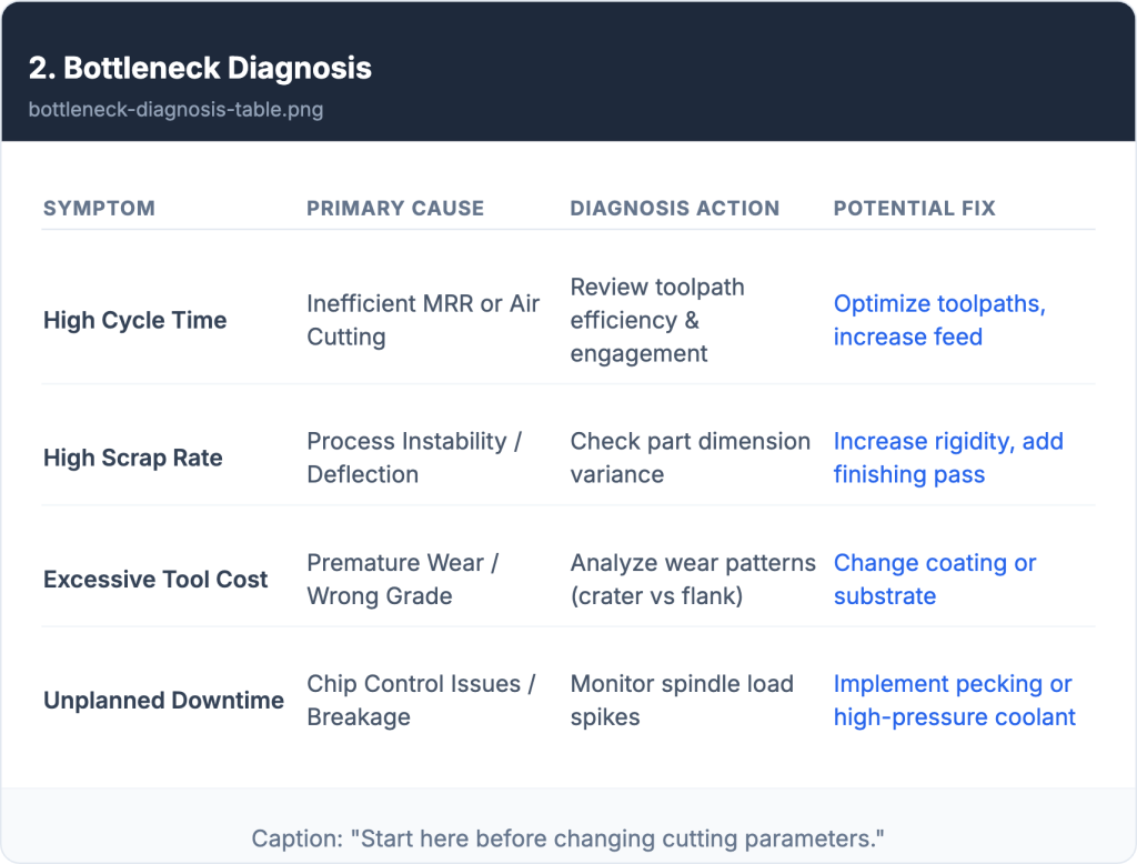
Bottleneck diagnosis (use this before changing parameters)
| Bottleneck | What you see | Typical root causes | First action |
|---|---|---|---|
| Cycle time too high | Long roughing passes | Wrong tool for MRR, conservative toolpaths | Confirm roughing geometry + chip evacuation |
| Scrap / rework | Surface marks, out-of-tolerance | Chatter, runout, thermal drift | Check runout + stickout + engagement strategy |
| Tool cost spikes | Frequent tool changes | Inconsistent setup, coating mismatch, overload at entry | Standardize setup + soften entry + inspect wear mode |
| Unplanned downtime | Breakage or sudden wear | Coolant mismatch, poor clamping, overload | Verify coolant delivery + reduce peak load spikes |
2) Strategy 1: Match tool type to operation (selection matrix)
A simple rule works well in aerospace: choose by operation first, then material/hardness, then machine rigidity (runout and stick-out).

Useful starting categories:
carbide end mills and carbide drills
Operation-based selection matrix (aerospace-friendly)
| Operation | Primary goal | Recommended geometry direction | Notes / boundary conditions |
|---|---|---|---|
| Roughing (high MRR) | Remove stock fast, stable chips | Stronger edge, variable helix/pitch, good chip space | Needs rigidity; manage entry strategy and stickout |
| Semi-finishing | Control stock for finish | Balanced geometry, stable engagement | Prioritize consistency over maximum MRR |
| Finishing | Surface finish & tolerance | Lower radial engagement, stable helix, sharp edge | Runout control becomes critical |
| Long reach / deep features | Reach & stability | Long-reach design, reduced ae, vibration control | L/D drives everything; avoid aggressive settings |
| Drilling (aerospace alloys) | Hole quality & chip control | Point geometry tuned for evacuation, stable margins | Coolant/peck strategy often decides success |
3) Strategy 2: Parameter windows that stay stable (3 tiers)
Aerospace shops often lose productivity by pushing one knob (feed or speed) while stability drops. A safer approach is to use
tiered parameter windows that match your setup consistency.
Parameter window framework
| Tier | When to use | What you change | What you watch |
|---|---|---|---|
| Conservative | New material, uncertain rigidity, runout risk | Lower ae/ap, moderate feed, stable entry | Edge chipping, chatter onset |
| Recommended | Stable setup and consistent coolant delivery | Balanced ae/ap, optimize fz for wear mode | Wear mode consistency (not just minutes) |
| Aggressive | Proven setup, controlled runout, strong evacuation | Increase MRR carefully, avoid peak load spikes | Thermal drift, finish/tolerance stability |
Stability levers that often beat “more feed”
- Reduce stickout (L/D) and improve clamping
- Measure and control runout
- Improve coolant targeting/pressure consistency
- Use engagement strategies that avoid overload spikes (entry/exit)
Engineer support (fast starting window)
If you share material grade + hardness + spindle limit + holder/runout + coolant type/pressure + stickout (L/D),
we can reply with a safe starter parameter window and a failure-mode adjustment checklist tailored to your setup:
send your machining details
4) Strategy 3: Reduce setup and tool-change time (without sacrificing quality)
Aerospace productivity gains often come from repeatability, not just higher cutting parameters:
- Standardize holders by operation (rough / finish / drill)
- Preset tools consistently (length/diameter offsets, wear criteria)
- Separate prototype settings from production settings
- Track wear mode (chipping vs flank wear) to avoid wrong “fixes”
5) Strategy 4: Stabilize tool life (runout, coolant, inspection)
Tool life variation is expensive in aerospace because it drives scrap, rework, and inspection load.
Stabilize these first:
- Runout & clamping (holder condition, contact surfaces)
- Coolant delivery (type, pressure, direction, chip evacuation)
- Entry strategy (reduce overload spikes)
- Wear monitoring (simple visual rules + change criteria)
If you want to compare end mill options by type and application:
Browse carbide end mills products
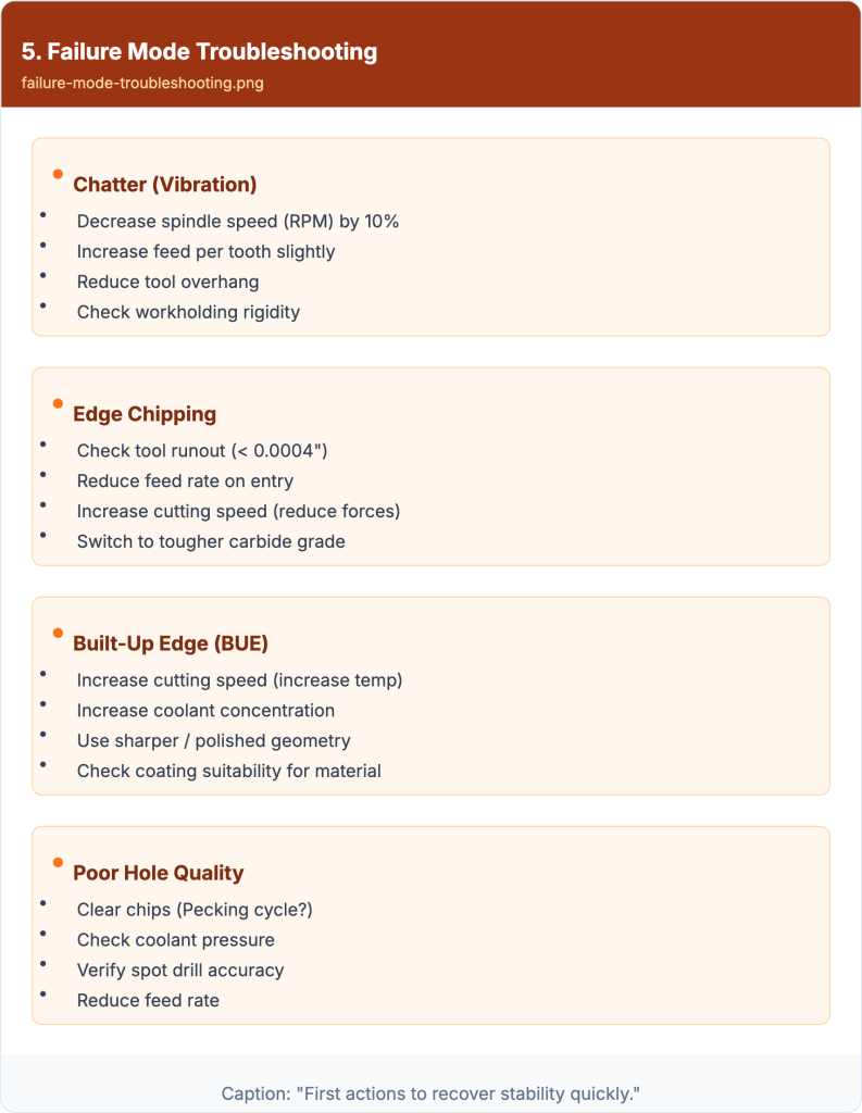
6) Quick troubleshooting table (symptom → cause → action)
| Symptom | Likely cause | First action | Verify |
|---|---|---|---|
| Chatter marks / vibration | Stickout too long, low rigidity, excessive ae | Reduce ae, shorten stickout, adjust helix/pitch direction | Chatter drops, finish improves |
| Edge chipping | Runout, overload at entry, too sharp edge for roughing | Check runout, soften entry, choose stronger edge geometry | Chipping reduces, wear becomes stable |
| Built-up edge (BUE) | Coolant mismatch, chip adhesion, unstable thermal conditions | Improve coolant targeting, revise window, improve evacuation | BUE reduces, finish stabilizes |
| Poor hole quality | Chip evacuation issues, point geometry mismatch | Improve coolant/peck strategy, confirm drill type/geometry | Hole size/finish improves |
7) RFQ checklist (send this to get accurate recommendations)
| Field | Example | Why it matters |
|---|---|---|
| Material grade + hardness | Ti-6Al-4V, HRC xx | Defines geometry/coating direction |
| Operation | Roughing / finishing / drilling | Tool choice and stability levers differ |
| Machine limits | Max RPM, rigidity notes | Sets realistic window |
| Holder & runout target | ER / heat-shrink; runout goal | Major driver of finish and tool life |
| Coolant | Flood / MQL / through-coolant + pressure | Chip control and thermal stability |
| Tool size & reach | Diameter, LOC/OAL, stickout | Defines L/D stability constraints |
| Target outcome | Ra, tolerance, cycle time | Helps prioritize tradeoffs |
FAQ
What’s the fastest way to improve productivity in aerospace machining?
Stabilize setup variables (runout, stickout, coolant delivery) before pushing parameters. Stability increases usable MRR without raising scrap risk.
Do higher cutting speeds always increase output?
Not always. If stability drops, scrap and rework can erase cycle-time gains. Use tiered windows and verify wear mode.
How do I choose between different carbide end mill types for aerospace work?
Choose by operation first (rough/finish/long reach), then adjust for material and your machine’s rigidity. Use the selection matrix above as a starting point.
What should I provide to get a useful parameter recommendation?
Material grade/hardness, machine limits, holder/runout target, coolant type/pressure, and stickout (L/D). Add target Ra/tolerance if finishing matters.
Next steps
Purchasing / Quotation
Send tool specification + quantity + target lead time, and include any inspection/report needs to Request for a quote



Request a Quote for Carbide Tools