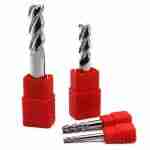
This carbide drill series features ultra-fine grain substrates (0.8μm), dual helix through-coolant design, AlCrN nano-coating (8-10μm), 140° self-centering point, and unequal helix flute geometry, primarily targeting deep hole, stack material, interrupted cut, and high-precision batch production applications.


Important Note: Actual machining results are comprehensively influenced by material hardness, machine rigidity, workholding method, coolant conditions, cutting parameters, and other factors. Specific performance must be confirmed based on actual working conditions.
Applicable Materials
The following material types can achieve satisfactory machining results under appropriate process conditions:
- 7075/7050 aluminum alloy and titanium alloy stack structures (30-50 layers)
- 42CrMo4 / 4340 high-strength quenched and tempered steel
- 17-4PH / 440C precipitation hardening stainless steel
- Inconel 718 / 625 nickel-based superalloys
- GGG70 high-strength ductile cast iron
- CFRP carbon fiber composite materials (requires delamination control)
- 316L medical-grade stainless steel implants
- ADC12 high-silicon die-cast aluminum alloy
Applicability Note: Machining results for the above materials depend on specific grades, heat treatment conditions, thickness, and machine conditions. Sample testing is recommended first.
When working with difficult-to-machine materials, refer to our machining hardened steel guide for parameter recommendations.
Typical Application Scenarios
This carbide drill series is commonly used in the following challenging machining scenarios (parameters must be adjusted based on specific conditions):
- Aerospace skin rivet holes (multi-layer stacks, H8 tolerance requirements)
- Automotive crankshaft deep oil holes (L/D ratio 15-25)
- Medical bone screw pilot holes (Ra 0.4 surface roughness, 0.01mm positional accuracy)
- Mold cooling channel deep holes and intersecting holes
- Wind turbine flange T-bolt holes (L/D ratio 20)
- Hydraulic manifold multi-hole group drilling
- Carbon fiber fuselage fastener holes (requires exit burr control)
Working Condition Requirements: The above application scenarios have high requirements for machine rigidity, coolant systems, and clamping precision. Tool life can reach 500-2000 holes (actual life varies by working conditions).
For aerospace machining applications, additional material traceability documentation may be required.
Design Features and Technical Parameters
Core Design Characteristics
| Feature | Parameter | Notes |
|---|---|---|
| Substrate Grain Size | 0.4-0.6μm | Ultra-fine grain carbide, specific model confirmation required |
| Coating Type | AlCrN nano-coating | 8-10μm thickness, suitable for high-temperature material machining |
| Coolant Structure | Dual helix through-coolant holes | Helps improve deep hole chip evacuation efficiency |
| Point Design | 140° self-centering point | Combined with S-shaped web, helps reduce entry offset |
| Flute Design | Unequal helix angle + variable pitch | Helps reduce machining vibration |
Precision Range Reference
- Straightness: Can achieve ≤0.02mm/100mm under suitable conditions (when L/D ratio ≤15)
- Hole position accuracy: Affected by machine, fixture, tool overhang, and other factors
- Exit quality: When machining CFRP materials, delamination and burr can be controlled with correct parameters
Important Reminder: The above precision data are reference values. Actual machining precision must be verified based on specific equipment, materials, and process conditions.
Material-Specific Drilling Parameters
Aluminum Alloys (7075/6061)
- Spindle speed: 3000-6000 RPM (depending on diameter)
- Feed rate: 0.15-0.25 mm/rev
- Coolant pressure: 50-70 bar
- Peck depth: Full depth capable with adequate cooling
- Common challenges: Built-up edge formation, chip evacuation in deep holes
Titanium Alloys (Ti-6Al-4V)
- Spindle speed: 800-1500 RPM
- Feed rate: 0.05-0.10 mm/rev
- Coolant pressure: 70-100 bar (minimum 70 bar required)
- Peck depth: Q=0.05mm for first 5 holes, then evaluate
- Common challenges: Work hardening, heat generation, chip control
Stainless Steel (316L/17-4PH)
- Spindle speed: 1200-2500 RPM
- Feed rate: 0.08-0.15 mm/rev
- Coolant pressure: 60-80 bar
- Peck depth: Q=0.1-0.3mm depending on L/D ratio
- Common challenges: Work hardening, built-up edge, chip stringiness
Superalloys (Inconel 718/625)
- Spindle speed: 600-1200 RPM
- Feed rate: 0.04-0.08 mm/rev
- Coolant pressure: 80-120 bar
- Peck depth: Q=0.05mm mandatory for first 10 holes
- Common challenges: Extreme heat, rapid work hardening, tool wear
Note: These parameters are starting points. Adjust based on machine capability, tool diameter, and hole depth. Contact our engineering team for application-specific recommendations.
Usage Recommendations and Precautions
Necessary Conditions
To fully utilize the performance of this drill series, the following basic conditions must be met:
- Coolant System: Through-coolant pressure ≥70 bar (below 50 bar may cause rapid wear)
- First-Piece Machining: For the first 3-5 holes, peck drilling cycle (Q≤0.05mm) is recommended; use full feed after tool stabilization
- Stack Materials: Must use segmented feed + periodic retraction for chip evacuation
- Pre-Centering: Pre-centering with 90° spot drill or flat end mill is recommended
- Regular Cleaning: After machining 200-300 holes, use compressed air + magnetic cleaning for internal flutes
- Temperature Control: When machining titanium alloys/superalloys, coolant temperature should be controlled at 28°C±0.5°C
- Storage and Maintenance: After use, ultrasonic cleaning + rust preventive oil protection + original tool tube storage
Unsuitable Scenarios
The following conditions are not recommended for this drill series, or process plans need to be re-evaluated:
- Insufficient machine rigidity or excessive spindle runout (>0.01mm TIR)
- No through-coolant system or insufficient coolant pressure
- Unstable workpiece clamping or vibration present
- Material hardness exceeds recommended range (RFQ confirmation required)
- Hole diameter tolerance requirements exceed tool capability range (tighter than H8)
For high precision end mill applications requiring tighter tolerances, please consult our engineering team.
Troubleshooting Common Drilling Issues
Problem: Drill Wanders at Entry
Possible Causes:
- No pre-centering performed
- Excessive spindle runout
- Point geometry worn or damaged
- Material surface not perpendicular to spindle axis
Solutions:
- Use 90° spot drill for pre-centering
- Check spindle TIR (<0.005mm required)
- Inspect drill point under microscope
- Verify workpiece setup squareness
Problem: Poor Hole Straightness
Possible Causes:
- Insufficient coolant pressure
- Drill flexing due to L/D ratio >15
- Uneven material hardness
- Worn drill margins
Solutions:
- Increase coolant pressure to 80+ bar
- Use peck cycle with Q=0.1-0.3mm
- Reduce feed rate by 20-30%
- Replace drill when margin wear exceeds 0.05mm
Problem: Chip Packing in Flutes
Possible Causes:
- Coolant flow blocked
- Feed rate too low
- Peck retraction insufficient
- Chip shape too long
Solutions:
- Clean coolant passages
- Increase feed per revolution
- Increase peck retraction distance
- Adjust coolant concentration (8-10% recommended)
Problem: Premature Tool Wear
Possible Causes:
- Excessive cutting speed
- Insufficient coolant flow
- Abrasive material content
- Coating delamination
Solutions:
- Reduce RPM by 15-20%
- Verify coolant pressure ≥70 bar
- Consider upgrading to diamond-coated drills for abrasive materials
- Inspect coating adhesion; if peeling, contact supplier
For additional support with die and mold applications, our technical team can provide on-site process optimization.
Factory Information and Quality Assurance
Production Capabilities
JYC Carbide related information:
- Factory Space: 270,000㎡
- Product range: 5,000+ SKU
- Active customers: 1,200+
- Cumulative shipments: 40 million pieces delivered
- Countries covered: 40+
Equipment and Certifications
- Grinding equipment: WALTER / ANCA / ROLLOMATIC
- Inspection equipment: ZOLLER / Laser / FEI / CMM
- Quality certifications: ISO 9001:2015 / 14001 / 45001 / 50001 / COC / SGS
Quality Assurance Notes:
- Inspection reports provided with shipment (COC files require additional confirmation)
- SGS third-party inspection reports Please check when FAQ
Technical Support and Quotation
Information Required for Quotation
To provide accurate product recommendations and parameter suggestions, please provide the following working condition information:
- Material grade and hardness (e.g., Ti-6Al-4V, HRC 35)
- Applications
- Product dimension or Drawing
- How many flutes
- Coating type
- Packing requirements
- Trade terms like FOB or other terms
- Any other requirements
Contact Information
- WhatsApp: +86 189-2679-8587
- Minimum order quantity: depends on products type, for regular stock items, MOQ are felxiable.
- Delivery time: Regular stock items shipped within 2-7 working days
Get Selection Guide: After providing detailed working condition information, our engineers will provide targeted product recommendations and parameter suggestions.
Frequently Asked Questions
What coolant pressure is required for deep hole drilling?
Minimum 70 bar through-coolant pressure is required for reliable chip evacuation. For L/D ratios exceeding 15 or when drilling superalloys, 80-120 bar is recommended. Insufficient coolant pressure is the primary cause of premature drill failure in deep hole applications.
Do you offer custom drill geometries?
Yes. we offer custom carbide drill (special point angles, step drills, custom coatings), minimum order quantity is flexiable with 2-4 week lead time. Provide detailed drawings including: hole diameter tolerance, dimension, HRC, etc. requirements, material specifications, and expected tool life targets.
How long should these drills last?
Tool life varies significantly by application: 500-2000 holes in aerospace titanium stacks, 1000-3000 holes in aluminum alloys, 200-800 holes in Inconel 718. Replace drills when: (1) margin wear exceeds 0.05mm, (2) hole diameter grows >0.02mm, (3) burr height increases, or (4) visible coating damage occurs.
Summary
This reliable carbide drill series is optimized for deep hole, stack, and interrupted cut challenging machining conditions. Under suitable machine conditions and process parameters, it can achieve longer tool life and stable machining quality.
Important Reminder: Tool performance is highly dependent on the matching of machine rigidity, coolant system, clamping method, and cutting parameters. Any performance commitments must be verified based on actual working condition testing. Sample trial cutting is recommended before batch use.
For comprehensive tooling solutions, explore our carbide end mill set selection guide to configure optimized tool kits for your machining operations.
Get a Quote – Contact our engineering team with your material specifications and machining requirements. We will provide customized recommendations based on your working conditions.


Request a Quote for Carbide Tools