Carbide Drill Bits: A Reliable Workhorse for Modern Precision Hole Making
Author: JYC Carbide Application Engineering TeamLast updated: May 27, 2026
In modern CNC machining, solid carbide drill bits are a mainstream solution for precision hole making in steel, tool steel, stainless steel, cast iron, and aluminum alloys. JYC Carbide tool Manufacturer They can reliably handle everything from pilot holes to medium and deep holes (around 3D–20D) when the drill design and cutting parameters match the application.
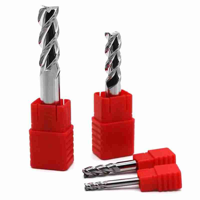
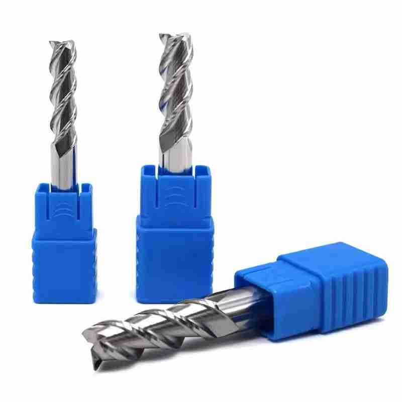

1. What Types of Holes Can Carbide Drills Cover?
With proper drill selection and a realistic process window, solid carbide drills can be used for most day‑to‑day hole types found in metal parts.
- Through holes, blind holes, stepped holes, and chamfered holes
- Medium and deep holes (approx. 3D–20D, depending on machine rigidity and coolant setup), especially when using carbide drills for deep hole machining
- Locating holes, dowel pin holes, and thread tap drill holes with tighter size requirements
- Cross holes, angled entries, thin‑wall holes, and stack‑up holes (with attention to guidance and chip evacuation)
- Typical mold features such as ejector pin holes, guide pillar holes, and cooling passages for die and mold machining applications
In many production jobs, the right carbide drill can complete roughing and semi‑finishing of standard hole features, and boring bars or reamers can then bring the hole to final size and surface finish where needed.
2. Typical Material Range for Solid Carbide Drills
The list below reflects common material groups where solid carbide drills are widely used in real production environments; exact cutting data should be set by an engineer based on part geometry, clamping stiffness, and coolant conditions.
2.1 Steels and Hardened Materials
Carbon steel, alloy steel, and tool steel are standard applications for carbide drills. Typical grades include P20, 718, NAK80, S136, SKD11, H13, and similar materials, usually in the HRC30–50 range. For hardened steel above this range, pairing drills with hardened steel end mills is often a practical choice.
Pre‑hardened and quenched steels up to about HRC30–55 can usually be drilled with solid carbide; for very high hardness above HRC55, milling with carbide end mills is often more practical for hole generation.
2.2 Stainless Steel and High‑Temperature Alloys
Common stainless steels such as 304, 316, 420, 440C, and 17‑4PH, covering austenitic, martensitic, and precipitation‑hardening stainless steels, are suitable for carbide drilling when chip control and coolant are well managed.
Nickel‑based superalloys such as Inconel 718 and GH4169 are drillable with solid carbide under reduced cutting speed and feed per tooth, combined with high‑pressure through‑coolant.
2.3 Titanium, Aluminum, and Non‑Ferrous Materials
For titanium alloys such as TC4 (Ti‑6Al‑4V), carbide drills can be used when high‑pressure coolant, rigid workholding, and conservative cutting data are in place, and many shops combine drilling with end mills for titanium machining in one setup.
Aluminum alloys and non‑ferrous metals like 6061 and 7075 support high‑speed drilling with suitable flute volume and chip evacuation, while copper, brass, and other non‑ferrous materials benefit from dedicated geometries and coatings designed for low built‑up edge (BUE) and good surface finish. For roughing and contouring in these alloys, shops often pair drills with solid carbide end mills for aluminum.
2.4 Cast Iron, Ductile Iron, and Special Materials
Cast iron and ductile iron (for example, gray cast iron, ductile iron, ADI) can be drilled effectively when chip control and coolant strategy are set correctly.
Composites and graphite such as CFRP and graphite require dedicated drill geometries and coatings, and should be treated as separate projects with a specific tool series and process plan.
Important: These material ranges describe where carbide drills are commonly applied in practice. They are not a claim that a single drill can handle every material or condition. For unusual materials or extreme conditions, consulting an engineer and running test cuts is strongly recommended before committing to production.
3. Where Carbide Drills Fit in the Machining Process
In a typical metal‑cutting process, carbide drills usually sit in the following stages.
3.1 Positioning and Rough Drilling
A center drill or spotting tool is used first when required, followed by a carbide drill to remove most of the material to depth. For aluminum and non‑ferrous parts this stage may be combined with CNC milling cutters in the same fixture.
3.2 Semi‑Finishing and Final Sizing
The drill often leaves 0.10–0.30 mm of stock for a boring bar or reamer, where the print calls for tighter tolerance and cylindricity. In aerospace parts this is commonly followed by solid carbide chucking reamers for final sizing.
3.3 One‑Step Hole Making and Difficult Features
When machine rigidity, tool runout, and process control are in good shape, certain hole tolerance levels (for example, around H7–H8) can be achieved directly with a ground carbide drill, followed by deburring or light correction as needed.
For aerospace, mold, and hydraulic manifold type parts with cross holes or angled entry holes, self‑centering point geometries and guiding features matter, and a short trial cut is often used to confirm behavior before releasing to production.
A common process example is: center drill → solid carbide drill for roughing and semi‑finishing → boring bar or reamer for final tolerance where required.
4. Design Features Compared to HSS Drills
The table below summarizes typical design differences between solid carbide drills and general‑purpose HSS drills, and how these differences usually show up in real shop conditions. The effects are trends rather than fixed promises, because they depend heavily on the specific application.
| Design element | Typical description | Trend in common shop conditions |
|---|---|---|
| Fine‑grain carbide substrate | Substrate hardness typically around 92–94 HRA with useful transverse rupture strength. | Better wear resistance than general HSS drills in tool steel and pre‑hardened steel. |
| Coating technology (AlTiN, nACo, DLC, etc.) | Coatings improve heat resistance, reduce friction, and limit built‑up edge (BUE). | Helps stabilize cutting edges and reduce wear in stainless, titanium, and superalloys. |
| Point angle and self‑centering geometry (approx. 135°–140°) | Balances cutting load and improves self‑centering capability. | Reduces dependence on center drilling and helps with angled entry conditions. |
| Internal coolant channels | Coolant reaches the cutting edges and flute roots directly. | Supports more stable chip evacuation and temperature control in 10D–20D holes. |
| Variable helix / variable pitch | Designed to damp vibration and break chips into shorter pieces. | Helps control long stringy chips in stainless and alloy steel. |
| Precision grinding and runout control | Diameter and shank ground to DIN 6535 / DIN 6537 and similar standards; shank tolerance up to h6 (ISO 286‑1). See also the DIN 6537 and DIN 6535 guide. | With proper toolholding and machine condition, can support H7–H8‑level hole size in many jobs. |
In practice, carbide drills usually deliver higher productivity and longer tool life than general HSS drills when matched correctly to the application, and actual improvements should always be confirmed by test cuts under defined conditions.
5. Accuracy and Tolerances for Carbide Drills
For turning‑milling centers and machining centers that handle volume hole making, tool accuracy and system runout directly impact hole size and location.
5.1 Diameter and Shank Tolerances
- Cutting diameter D ≤ 12 mm: diameter tolerance 0 to +0.020 mm.
- Cutting diameter D > 12 mm: diameter tolerance 0 to +0.030 mm.
- Corner radius / R value: radius tolerance ±0.01 mm.
- Shank tolerance: shank ground to h6 according to ISO 286‑1, suitable for ER collets, hydraulic chucks, and heat‑shrink holders.
5.2 Runout and System Accuracy
Under clean and proper clamping conditions, tool runout at the clamping location in the range of approximately 0.005–0.01 mm is realistic for many diameters and holders. The final hole position and form error in the workpiece will also depend on spindle accuracy, fixture stability, and stack‑up, and many precision hole applications target total indicated runout (TIR) on the part within about 0.05 mm. For more details on standards and tolerances, you can refer to the carbide standards and specifications FAQ.
Note: These values describe a typical level of tool manufacturing and application capability. For any specific job, the drawing and technical agreement always take priority over generic reference values.
6. Practical Application Tips for CNC Machining
To help process engineers and machinists get stable performance from carbide drills, the points below can be used as a setup and troubleshooting checklist.
6.1 Start from the Right Material Data
Identify the material and hardness first. Use different cutting speeds Vc and feed per tooth fz for different ISO material groups (P/M/K, etc.) and hardness ranges such as HRC30–45 vs. HRC45–55, starting from the toolmaker’s recommended window.
6.2 Control Runout at the Toolholder
Combine h6 shanks with high‑precision chucks and verify runout near the cutting edges. Excessive runout is a common root cause of poor tool life and inconsistent hole size, especially in small diameters and deep holes.
6.3 Coolant Strategy and Chip Evacuation
For medium and deep holes, stainless steels, titanium, and high‑temperature alloys, through‑coolant drills with high‑pressure coolant are strongly preferred. External coolant setups may require shorter peck depths, lower feedrates, and more frequent chip evacuation cycles.
6.4 Test Cuts Before Ramping Up
On new parts or new materials, start with a safe Vc and fz, then watch chip shape, hole wall color, and wear pattern. Move toward more aggressive data only after behavior is stable and repeatable across several parts.
6.5 Know the Limits of Drilling
For very high hardness above about HRC55, extreme thin‑wall sections, or long overhangs, switching to small‑diameter milling strategies or step drilling and boring can be more robust than a single deep drill pass.
These suggestions are based on common shop experience and are not a substitute for detailed parameter tables and documented trial cuts for a specific part. For more drilling and milling tips, see the Machining Knowledge section.
7. Plant Capability and Quality Signals
For purchasing and engineering teams, supplier capability and quality control are critical trust signals as well as practical concerns.
7.1 Company Profile and Scale
JYC Carbide / Jinyuchang Industrial Technology Co., Ltd operates under the brand “JYC Carbide.” Official website: carbide-factory.com. The supported manufacturer approximate plant area is 270,000 m², with more than 5,000 active SKUs in the catalog, over 40 million pieces delivered in total, and more than 1,200 active customers in over 40 countries and regions.
7.2 Equipment and Metrology
Tool grinding is carried out on CNC grinders such as P3 WALTER, ANCA, and ROLLOMATIC. Measurement and inspection use systems such as ZOLLER presetters, laser measuring equipment, and CMMs (including FEI systems) for diameter, runout, and form checks.
7.3 Management Systems and Documentation
The supported manufacturer has implemented ISO 9001, ISO 14001, ISO 45001, and ISO 50001 management systems. Outgoing inspection reports and certificates of conformity (COC) can be provided with shipments. If a third‑party report from a testing organization such as SGS is needed, this can be discussed and arranged as a separate step for the project.
8. Application Limits and Risk Notes for Carbide Drilling
To avoid any misunderstanding that a single carbide drill can solve every hole‑making problem, the following limits are important for process planning.
- Tool life and productivity vary with material, hardness, machine condition, and setup, so fixed “life improvement factors” are not realistic without a defined benchmark and test conditions.
- Thick multi‑layer stacks, heavy weld overlays, parts with severe casting defects, or highly porous materials often require dedicated testing and may not follow standard speed and feed charts.
- For very tight tolerances such as IT6 or IT5, a combination of drilling plus boring or reaming is usually more reliable than drilling alone, and any one‑shot drilling approach should be validated in controlled trials.
- Any cutting data, hardness ranges, or D‑ratios mentioned here are general engineering reference values, not guarantees for every machine and setup; the final reference should always be the part print, agreed technical specification, and signed‑off test results.
9. Contact and RFQ Process for Carbide Drill Applications
If you need a carbide drill solution tailored to your plant’s conditions—material, hole depth, annual volume, machine type, and toolholding—the steps below help engineers respond with relevant suggestions.
- Send an RFQ via the website form or the dedicated carbide drills RFQ page, or reach out via WhatsApp at: 0086‑189‑2679‑8587.
- When you contact us, it helps to include: material grade and hardness; hole diameter and depth (for example, 6 mm × 60 mm, 10D); any cross holes, angled entries, or thin‑wall sections; your current tool model; and what is going wrong (for example, chipping at entry, drill breakage at 5D, unstable hole size, poor chip evacuation).
- For jobs involving tighter tolerances or special materials, a small‑lot trial run is usually recommended, after which an engineer can fine‑tune the drill geometry or coating and give more specific cutting data.
The focus is on practical, application‑oriented recommendations rather than absolute promises.
Ready to optimize your carbide drilling process?Request a carbide drill RFQ
We will provide recommendations customized to your actual machining conditions — tooling is suggested only after we understand your material, machines, and targets.
FAQ
What materials can your carbide drill bits handle?
Our solid carbide drills cover common steels, stainless, cast iron, aluminum alloys, titanium, and nickel alloys, with parameters adjusted by material group and hardness.
How deep can I drill with solid carbide drills?
aWith proper rigidity and through‑coolant, most production jobs run reliably around 5–10D; 15–20D and beyond should be treated as deep‑hole projects with test cuts.
Do I always need a pilot or spot drill before carbide drilling?
Not always. Self‑centering carbide geometries can drill from flat surfaces directly, but a spot or pilot is helpful on angled, curved, or hard‑scale entry faces
About the author: This guide is prepared by the JYC Carbide Application Engineering Team, with experience in CNC hole making for automotive, die & mold, and general machining plants across more than 40 countries. The content is reviewed regularly to stay aligned with current machining practices and international standards.


Request a Quote for Carbide Tools