Metric End Mill Selection Guide: Geometry, Tolerances and Material Fit
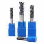
A metric end mill is a solid carbide end mill with cutting diameters specified in millimeters, typically available in 0.1 mm increments from Ø0.1 to Ø25.0 mm. In manufacturing markets where drawings, CNC programs, and tooling libraries all use metric units — including Europe, China, Japan, Korea, and most of Southeast Asia — a metric tool set eliminates the unit conversion step between drawing and program.


This guide covers series selection by material, precision specifications, geometry guidance, and what to confirm before ordering. For a broader overview of available geometries, see carbide end mills or the full milling cutter range.
1. What a Metric End Mill Actually Defines
The term “metric end mill” refers to the unit system used for the cutting diameter, not a specific geometry or performance grade. Key characteristics include:
Using metric tooling does not by itself guarantee dimensional accuracy. Final part accuracy still depends on machine condition, spindle runout, holder system, clamping rigidity, coolant delivery, and toolpath. A metric end mill reduces one source of potential error — unit conversion — but does not eliminate the others.
2. Precision Specifications (JYC Carbide Standard)
The following are JYC Carbide’s published tolerance limits for solid carbide end mills. Applications requiring tighter tolerances should be confirmed through RFQ against drawing requirements.
| Parameter | Tolerance | Reference Standard |
|---|---|---|
| Cutting diameter D ≤12 mm | 0 − 0.020 mm | — |
| Cutting diameter D >12 mm | 0 − 0.030 mm | — |
| Shank tolerance | h6 | ISO 286-1 |
| Runout TIR (D ≤12 mm) | ≤0.05 mm | — |
For shank tolerance definitions and the difference between h5 and h6 fit, see the DIN 6537 and DIN 6535-HA standards reference page. If your project specifies tighter runout or diameter tolerance, confirm against drawing before ordering.
3. Material Range and Series Reference
Metric end mills are available across all standard material groups. Series selection should follow workpiece material and hardness, not tool diameter alone.
| Series | Material Group | Hardness Range | Typical Grades |
|---|---|---|---|
| NCG | General steel | HRC≤45 | Carbon steel, alloy steel |
| NCP | Pre-hardened steel | HRC≤55 | NAK80, P20, 718 |
| NCPX | Stainless steel | — | 420, 440C, 17-4PH, 1Cr18Ni9Ti |
| NCH | Hardened steel | HRC45–65 | SKD11, D2, H13, DC53 |
| NCJ | Small-diameter precision | — | D1–D6 mm fine features |
| AU | Aluminum | — | 6061, 7075, aerospace alloys |
| AUR | Aluminum roughing | — | High-volume aluminum removal |
For stainless steel applications, the stainless steel specific flat end mill covers 420, 440C, 17-4PH, and austenitic grades. For hardened steel at HRC45–65, see hardened steel end mills.
For titanium (TC4, TC11) and superalloys (Inconel 718, GH4169), flute geometry, coating, and coolant strategy should be confirmed individually. Do not apply a single parameter set across all difficult materials.
4. Geometry Selection by Material
Flute Count
- 2–3 flute
- 4 flute: General steel and pre-hardened steel (NCG/NCP) — standard finish and productivity balance
- 4–6 flute: Hardened steel and stainless steel (NCH/NCPX) — shorter cutting edge engagement, better heat management
Coating Reference
- Coating performance depends on substrate quality, edge preparation, heat load, and coolant delivery — not the coating name alone. For aluminum finishing with 2-flute geometry, see the 2-flute ball end mill for aluminum as a reference geometry.
5. Common Applications
Metric end mills are commonly used in:
- Medical implant contour milling and precision slot features
- Aerospace structural component profiling and fastener hole preparation
- Electronics components: antenna slots, card slots, and precision step surfaces
- Any precision part where drawing, program, and tooling are all in metric — eliminating one layer of potential conversion error
Metric end mills are commonly used in:
For a broader breakdown by industry and part type, see the applications page.
6. Practical Selection Tips
- Use h6 shank for standard holders
- Do not use aluminum-geometry tools on steel: 2-flute high-helix tools have insufficient edge support for steel and will wear faster or chatter
- Metric units reduce one error source, not all: spindle condition, holder runout, clamping, and toolpath all affect final part accuracy independently
- In deep cavity or long-reach setups, address stickout and holder rigidity before adjusting cutting parameters
- For interrupted cuts and thin-wall features, variable helix and unequal pitch geometries reduce vibration tendency — standard equal-pitch tools are not recommended for these conditions
- Replace tools before diameter tolerance drifts to the lower limit: worn cutting diameter causes dimensional drift and surface quality degradation that is difficult to correct in-process
7. Frequently Asked Questions
What is the difference between h5 and h6 shank tolerance?
Both are defined under ISO 286-1. h6 is the standard shank tolerance for most collet and hydraulic holder systems. h5 has a narrower tolerance band and is used where assembly repeatability requirements are tighter. Check the holder manufacturer’s recommended fit range before specifying h5.
Can a metric end mill machine inch-dimensioned parts?
Yes. Tool unit system does not limit what workpiece dimensions it can cut. The benefit of metric tooling is in simplifying the programming step when drawings and CNC machines both use metric. When machining inch drawings, the same unit conversion requirement exists regardless of tool unit system.
How should I select a metric end mill set for a new shop setup?
End mill set configuration depends on the primary material group and machining stages. See the carbide end mill set selection guide for configuration recommendations by application type.
8. What to Confirm Before RFQ
To receive a useful specification recommendation, confirm the following before submitting an inquiry:
- Machining zone: slot, step, cavity, sidewall, or precision fit surface
- Required cutting diameter, flute count, overall length, flute length, and actual stickout
- Machine type, spindle speed range, holder system, and coolant method
- Current issue: chipping, chatter, dimensional drift, surface marks, or poor chip evacuation
- Machining stage: semi-finish to finish, or direct finish after heat treatment
To receive a useful specification recommendation, confirm the following before submitting an inquiry:
9. Request a Specification
Metric end mills are a practical choice when drawings, programs, and tooling all use the same unit system. Whether they are the right tool for your specific part depends on material, hardness, machine setup, holder, and toolpath — not unit system alone.
Submit your drawing, material grade, hardness, machining area, current tool issue, machine model, holder system, stickout, and coolant method. JYC Carbide will provide a series recommendation, a starting parameter range, and a shipment inspection report based on your RFQ. Sample policy, lead time, and non-standard requests are confirmed during inquiry.



Request a Quote for Carbide Tools