Sourcing solid carbide ball nose end mills presents unique procurement risks because minor profile errors directly cause dimensional deviations, poor surface finish, and premature tool chipping during 3D contouring and mold profiling. A qualified tooling supplier must maintain documented quality control at every stage, from carbide rod substrate verification to final coating adhesion.
For procurement managers and tooling engineers, evaluating a supplier’s quality control protocol before issuing purchase orders prevents costly mold rework, machine downtime, and batch-to-batch inconsistency. This guide outlines the essential inspection checkpoints, measurement methods, and RFQ criteria required to verify a manufacturer’s QC capability.
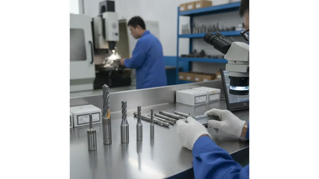
Why Carbide Ball Nose End Mill Geometry Demands Multi-Stage Inspection
Ball nose end mills feature complex continuous curvature where any deviation in radius accuracy, flute symmetry, or tangential blending causes immediate gouging or uneven cusp heights on 3D sculpted surfaces. Multi-stage quality control ensures that errors are intercepted before tools reach finished packaging.
Relying solely on outer diameter checks misses radius form errors, resulting in scrap parts during high-precision copy milling.
Geometry verification requires measuring the continuous hemispherical radius, center-cutting gash geometry, and peripheral-to-ball blend transitions.
Request documented profile inspection charts for initial tooling samples before approving recurring production runs.
Unlike standard square end mills where the primary cutting edges are straight, a ball nose cutter engages the workpiece across varying effective cutting diameters and surface speeds. At the exact tool center, the surface speed drops to zero, making center gash symmetry and chisel edge geometry critical for chip evacuation and plunge cutting.
Furthermore, the transition zone where the hemispherical ball merges into the cylindrical peripheral flute must be seamlessly tangential. Even a 5-micron step at this blend point creates visible witness lines on finished mold cavities. Comprehensive ball nose end mill quality control requires specialized optical and coordinate verification rather than basic contact caliper checks.
Decision checkpoint
- Confirm whether your supplier verifies the complete radius arc or only inspects nominal tip diameter.
- Ensure center gash geometry is checked under magnification to prevent center-point chipping under high axial loads.
The 5 Critical Quality Control Stages in Ball Nose Manufacturing
A robust manufacturing QC system covers five sequential checkpoints: raw carbide substrate testing, post-grinding radius and diameter verification, runout and concentricity measurement, coating adhesion assessment, and post-coating batch sampling.
Skipping upstream inspections leads to premature failure where high-cost coatings are applied over defective geometries or flawed substrates.
Auditing a supplier’s quality management system requires checking their gating criteria across each phase of production. The table below details the essential parameters and methods that comprise a standard carbide ball nose end mill QC checklist.
| Inspection Stage | Target Quality Parameter | Standard Measurement Method | Failure Risk If Missed |
|---|---|---|---|
| 1. Substrate Inspection | Carbide rod grain size, density, hardness, straightness | Ultrasonic testing, hardness testing, runout gauge | Internal porosity, micro-cracks, unexpected catastrophic tool breakage |
| 2. Post-Grinding Geometry | Ball radius (R), profile form, flute spacing, relief angles | Non-contact optical profile projector, CMM measurement | Dimensional inaccuracies, cusp height variance, rapid edge wear |
| 3. Runout & Concentricity | Radial runout tolerance, shank concentricity | Laser measurement system, precision dial indicator | Uneven flute loading, chatter, shortened spindle and tool life |
| 4. Surface & Edge Quality | Cutting edge roughness, micro-chipping, honing radius | High-magnification digital microscope | Premature edge breakdown, unstable cutting forces |
| 5. Coating Quality | Coating thickness, adhesion, surface droplet defect rate | Calotest, scratch test, optical inspection | Coating flaking, thermal degradation, abrasive wear |
Decision checkpoint
- Audit whether the supplier conducts pre-coating optical inspection to catch grinding burrs and edge micro-fractures.
- Verify that the supplier maintains traceable batch logs linking raw carbide rod lots to finished tool batches.
Radius Form and Runout Verification: Measuring Methods Explained
Precise radius verification utilizes multi-axis optical tool presetters and non-contact 3D optical scanning to map the ball envelope, while ball nose end mill runout tolerance is verified by rotating the tool in high-precision inspection collets.
Excessive runout causes one flute to absorb the entire chip load, triggering severe tool vibration and uneven surface finishes.
Tool runout should be measured both at the tool shank and at the full radius tip under controlled rotation.
Specify maximum allowable runout at the tip when procuring long-reach or small-diameter ball nose tools.
In 3D copy milling, CMM measurement ball nose radius inspection evaluates the entire 180-degree hemispherical form. Advanced optical systems project a high-resolution contour overlay to calculate deviations from the theoretical profile across multiple angular orientations.
Similarly, flute ball nose end mill performance depends heavily on radial runout. When rotating in high-speed spindles, even minor runout exaggerates dynamic imbalance. Quality suppliers test total indicator reading (TIR) at multiple points along the flute and ball apex to guarantee balanced cutting force distribution.
Understanding Optical vs. Tactile Probing for Ball Profiles
Non-contact optical inspection avoids deflection errors common when tactile probes touch ultra-fine ball tips (such as micro-diameter end mills). For larger profile tools, tactile CMM scanning provides cross-sectional profile verification along multiple planes to confirm true sphericity.
Decision checkpoint
- For standard milling, inspect overall runout tolerance; for micro and finishing applications, require multi-point TIR data.
- Confirm that measuring equipment calibration records comply with documented metrology standards.

Batch Quality Control: Sampling Ratios vs. 100% Inspection
While raw material and final packaging commonly follow Acceptance Quality Limit (AQL) statistical sampling, critical geometric dimensions and radial runout on precision finishing tools should undergo 100% automated or high-ratio optical verification.
Relying solely on loose batch sampling risks receiving out-of-spec tools in high-volume shipments, leading to sporadic batch failures during unattended machining.
Align inspection levels with part tolerances: request 100% radius verification for high-precision finishing series and standard AQL for general roughing tools.
Effective batch quality control ball nose end mill strategies differentiate between general-purpose roughing tools and precision finishing cutters. In standard mass production of wholesale carbide end mills, suppliers typically inspect the first and last parts of a grinding run alongside periodic sample intervals.
However, for high-precision series—such as those used in aerospace blisk profiling or hardened die manufacturing—a 100% inspection protocol for ball radius and total runout is standard. Evaluating the supplier’s sampling policy clarifies whether their quality regime fits your production risk profile.
Decision checkpoint
- Define whether your project requires 100% inspection reports or standard batch certificates of conformance.
- Establish clear defect acceptance thresholds (AQL levels) in advance of mass production orders.
What Technical Information to Send for a Tooling Quote or QC Review
To establish precise quality inspection criteria, buyers should provide the exact workpiece material and hardness, milling operation, critical tool dimensions, machine setup, target tolerances, and expected batch volume.
Incomplete RFQ parameters force suppliers to assume standard commercial tolerances, which may not satisfy critical 3D finishing demands.
Tool inspection boundaries must mirror the workpiece tolerances and operating constraints specified in the engineering drawing.
Include all six operational data points in your initial request to ensure alignment between supplier QC and production requirements.
When submitting an RFQ or requesting a quality assessment from a carbide tool manufacturer, providing thorough application parameters ensures the quotation includes appropriate grinding tolerances and inspection protocols.
Whether selecting a 2-flute ball nose carbide end mill for aluminum contouring or a multi-flute coated cutter for hardened steel, submitting the following data points prevents specification gaps:
- Workpiece material specification and heat treatment hardness (e.g., HRC rating)
- Specific machining operation (3D copy milling, roughing, semi-finishing, or mirror finishing)
- Tool geometry: cutting diameter, ball radius, flute count, flute length, reach, and shank diameter
- Machine tool and tool holding interface (spindle taper, clamping type, dynamic runout limits)
- Part drawing with explicit surface finish (Ra) and dimensional profile tolerances
- Expected batch quantity, delivery schedule, and required inspection documentation level
Decision checkpoint
- Send 2D/3D part drawings showing tight-tolerance contours to define required ball radius tolerance bands.
- Specify if coating adhesion or substrate grain certificates are mandatory for vendor qualification.
Frequently Asked Questions
What is the typical radius tolerance for a precision carbide ball nose end mill?
Radius tolerances depend on the specific tool family and grade. Standard commercial ball nose end mills typically maintain radius tolerances within ±0.010 mm to ±0.020 mm, whereas high-precision mold-finishing series often hold tolerances within ±0.005 mm or tighter. Always verify product-specific catalog tolerances.
How does ball radius of the carbide ball nose end mill error affect 3D surface finish?
If the ball radius deviates from nominal, programmed CAM toolpaths will either over-cut or leave excess material, resulting in uneven cusp heights, surface waviness, and extended manual polishing or part rejection.
Why is center cutting edge inspection critical on ball nose tools?
Because cutting speed approaches zero at the center tip, an improperly ground center gash or asymmetric chisel edge cannot evacuate chips effectively, causing cutting edge buildup, micro-chipping, or tool fracture during shallow plunge cuts.
What documentation should I request to verify batch quality control?
Buyers can request a Certificate of Analysis (CoA) or Certificate of Conformance (CoC), grinding inspection reports detailing radius and runout measurements, and substrate material traceability records.
Discuss Your Tooling Requirement
Send the workpiece material, hardness, operation, tool diameter, reach, machine and holder details for a bounded tooling review.
Send your machining requirements to TUNGVARA.


